Difference between revisions of "Dry ponds"
ChristineLN (talk | contribs) |
ChristineLN (talk | contribs) |
||
| (38 intermediate revisions by 2 users not shown) | |||
| Line 16: | Line 16: | ||
</imagemap> | </imagemap> | ||
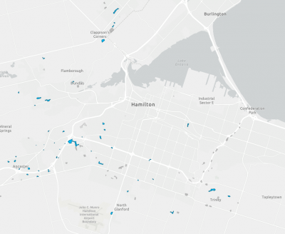
| − | [[File: | + | [[File:Screenshot 2025-08-29 092912.png|400px|thumb|right|link=https://open.hamilton.ca/datasets/SpatialSolutions::stormwater-management-facilities/explore?filters=eyJGQUNJTElUWV9UWVBFIjpbIkRyeSBQb25kIl19&location=43.231533%2C-79.840637%2C11.00&style=FACILITY_TYPE|Click on the image to open a map of dry ponds in Hamilton.]] |
| + | |||
See also [[Water squares]] | See also [[Water squares]] | ||
{{TOClimit|2}} | {{TOClimit|2}} | ||
| − | |||
==Overview== | ==Overview== | ||
| Line 28: | Line 28: | ||
*erosion management, | *erosion management, | ||
*incorporating into parks and other green recreational spaces, and | *incorporating into parks and other green recreational spaces, and | ||
| − | *distributing across a larger development site.}} | + | *distributing across a larger development site.}} |
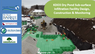
| − | [[ | + | [[File:Screenshot 2025-08-25 144851.png|400px|thumb|right|link=https://sourcetostream.com/2024-track-1-day-1-denich-eves/|Click on the image to read about an infiltration facility with OGS pre-treatment located beneath an existing dry-pond in the Lake Simcoe Watershed (Denich & Eves, 2024)<ref>Dennich, C. & Eves, C. 2024. KDO3 Dry Pond Sub-surface Infiltration Facility Design, Construction & Monitoring. Source to Stream Conference Presentation. https://sourcetostream.com/2024-track-1-day-1-denich-eves/</ref>.]] |
| − | + | ||
| + | Click the button below to read about a case study of a dry pond on the UTSC campus. | ||
| + | |||
| + | {{Clickable button|[[File:UTSC bioretention.PNG|130 px|link=https://sustainabletechnologies.ca/app/uploads/2015/07/U-of-T-Scarborough.pdf]]}} | ||
| + | |||
| + | ===STEP Training=== | ||
| + | Click the button on the left to register for training on SWM pond inspection and maintenance and the button on the right to learn about wet ponds: | ||
| + | |||
| + | {{Clickable button|[[File:Screenshot 2025-08-29 101010.png|150px|link=https://sustainabletechnologies.ca/lid-swm-inspection-maintenance-training/]]}} {{Clickable button|[[File:Screenshot 2025-08-29 101218.png|150 px|link=https://wiki.sustainabletechnologies.ca/wiki/SWM_ponds]]}} | ||
==Planning considerations== | ==Planning considerations== | ||
| Line 102: | Line 110: | ||
*no steeper than 1:3 to permit vegetation stabilization and maintenance/amenity access (except where pond <0.5 m deep) | *no steeper than 1:3 to permit vegetation stabilization and maintenance/amenity access (except where pond <0.5 m deep) | ||
*stepped or benched slopes possible depending on maintenance access (Ballard et al., 2015)<ref name=Ballard/> | *stepped or benched slopes possible depending on maintenance access (Ballard et al., 2015)<ref name=Ballard/> | ||
| + | *recommended that the grading of the pond side slopes be terraced with an average slope of 4:1 or flatter. | ||
|- | |- | ||
|[[Dry ponds#Inlet|Inlet]] | |[[Dry ponds#Inlet|Inlet]] | ||
| Line 131: | Line 140: | ||
===Volume=== | ===Volume=== | ||
| − | |||
| − | |||
| − | |||
| − | |||
| − | |||
| − | |||
| − | |||
| − | |||
| − | |||
| − | |||
| − | |||
| − | |||
| − | |||
| − | |||
| − | |||
| − | |||
| − | |||
| − | |||
The surface storage volume of a dry pond (''A<sub>p</sub>'') is determined: | The surface storage volume of a dry pond (''A<sub>p</sub>'') is determined: | ||
<math>A_{p}=\frac{RVC_T\times A_{c}}{f'\times t}</math> | <math>A_{p}=\frac{RVC_T\times A_{c}}{f'\times t}</math> | ||
| Line 156: | Line 147: | ||
*''f''' = design infiltration rate (mm/hr) | *''f''' = design infiltration rate (mm/hr) | ||
*''t'' = [[drainage time|time permitted for ponding to infiltrate]] (hrs) (typically 48 hours)}} | *''t'' = [[drainage time|time permitted for ponding to infiltrate]] (hrs) (typically 48 hours)}} | ||
| − | |||
| − | |||
===Detention time=== | ===Detention time=== | ||
| Line 214: | Line 203: | ||
{| class="wikitable" style="width: 900px;" | {| class="wikitable" style="width: 900px;" | ||
| − | |+'''Visual Indicators Framework - Bioretention/Swales''' | + | |+'''Visual Indicators Framework - Bioretention/Swales/Dry Ponds''' |
|- | |- | ||
!<br>'''Size Fraction (i)''' | !<br>'''Size Fraction (i)''' | ||
| Line 268: | Line 257: | ||
===Inlet=== | ===Inlet=== | ||
[[File:Screenshot 2025-08-20 115733.png|400px|thumb|Dry pond inlet (MOE, 2003)<ref name="MOE"></ref>]] | [[File:Screenshot 2025-08-20 115733.png|400px|thumb|Dry pond inlet (MOE, 2003)<ref name="MOE"></ref>]] | ||
| − | The number of [[Inlet|inlets]] into the pond should be minimized. To reduce [[Erosion|erosion]] risk, the use of environmental stone or interlocking blocks with large openings that support vegetative growth is recommended at the inlet. A flow deflector or energy dissipation blocks may also be installed to limit scour and prevent the resuspension of previously settled pollutants from the pond bottom (MOE, 2003)<ref name="MOE"></ref>. | + | The number of [[Inlet|inlets]] into the pond should be minimized. The invert of the inlet pipe is set at the maximum design water level in the pond. To reduce [[Erosion|erosion]] risk, the use of environmental stone or interlocking blocks with large openings that support vegetative growth is recommended at the inlet. A flow deflector or energy dissipation blocks may also be installed to limit scour and prevent the resuspension of previously settled pollutants from the pond bottom (MOE, 2003)<ref name="MOE"></ref>. |
===Outlet=== | ===Outlet=== | ||
| − | [[File:Screenshot 2025-08-20 115140.png|400px|thumb|Dry pond outlet (MOE, 2003)<ref name="MOE"></ref>]] | + | [[File:Screenshot 2025-08-20 115140.png|400px|thumb|Dry pond outlet (MOE, 2003)<ref name="MOE"></ref>.]] |
| − | The performance of a dry pond can be enhanced via a shallow micropool at the outlet which concentrates finer sediment and reduces re-suspension. The micropool is normally planted with hardy wetland species such as [[Wetlands: Plants|cattail]] (MOE, 2003)<ref name="MOE"></ref>. | + | The outlet should be located in the pond embankment wherever possible for ease of maintenance and aesthetics. The performance of a dry pond can be enhanced via a shallow micropool at the outlet which concentrates finer sediment and reduces re-suspension. The micropool is normally planted with hardy wetland species such as [[Wetlands: Plants|cattail]] (MOE, 2003)<ref name="MOE"></ref>. A reverse sloped pipe makes the outlet more resilient to clogging (MOE, 2003)<ref name="MOE"></ref>. |
| Line 285: | Line 274: | ||
*a naturalized landscape approach should be used which strives for a [[Plant lists|vegetation]] community with long-term sustainability and no maintenance requirements (MOE, 2003)<ref name="MOE"></ref>. | *a naturalized landscape approach should be used which strives for a [[Plant lists|vegetation]] community with long-term sustainability and no maintenance requirements (MOE, 2003)<ref name="MOE"></ref>. | ||
| − | See [[Turf|Salt-Tolerant Turf Grasses]], [[Shrubs: List]], and [[Trees: List]] for a list of native species which could be planted in the buffer strip.< | + | See [[Turf|Salt-Tolerant Turf Grasses]], [[Shrubs: List]], and [[Trees: List]] for a list of native species which could be planted in the buffer strip. |
| + | |||
| + | ===Planting Strategy=== | ||
| + | Depending upon the proposed planting strategy, these maximum storage depths may be reduced to 1 to 1.5 metres. It is anticipated, however, that the dry pond will not be actively planted in the extended detention portion due to harsh growing conditions (frequent wetting/drying). The planting approach for a dry pond is typically less intensive than for a wet pond, involving fewer species and lower planting density. Vegetation is generally organized into three zones according to soil moisture conditions: | ||
| + | |||
| + | *Extended detention area | ||
| + | *Flood fringe area (for combined quality/quantity SWMPs) | ||
| + | *Upland area | ||
| + | |||
| + | Growing conditions in the extended detention area of a dry pond are more challenging than in a wet pond because there is no permanent pool to moderate moisture levels. As a result, this zone requires particular attention to ensure that desired plant species establish successfully (MOE, 2003)<ref name="MOE"></ref>. | ||
| + | |||
| + | ==Performance== | ||
| + | {| class="wikitable" style="float:right; margin-left:15px;" | ||
| + | |+ style="text-align:center;" | Recommended storage volumes per ha by catchment imperviousness for continuous flow dry ponds with basic protection (MOE, 2003)<ref name="MOE"></ref> | ||
| + | ! Imperviousness of Catchment | ||
| + | ! Storage Volume (m³/ha) | ||
| + | ! Permanent pool (extended detention) (m³/ha) | ||
| + | |- | ||
| + | | 35% | ||
| + | | 90 | ||
| + | | 50 | ||
| + | |- | ||
| + | | 55% | ||
| + | | 150 | ||
| + | | 81 | ||
| + | |- | ||
| + | | 70% | ||
| + | | 200 | ||
| + | | 89 | ||
| + | |- | ||
| + | | 85% | ||
| + | | 240 | ||
| + | | 107 | ||
| + | |} | ||
| + | |||
| + | Stormwater ponds and constructed wetlands are designed to meet water quality targets based on drainage area imperviousness. Pollutant removal occurs mainly in the permanent pool, with effectiveness depending on hydraulic residence time—longer times improve sedimentation and biological uptake. In Ontario, most facilities must achieve 80% TSS removal, with storage requirements based on a 24-hour drawdown time (MOE, 2003)<ref name="MOE"></ref>. | ||
| + | |||
| + | Dry ponds may include a deep pool in the sediment forebay to minimize scour and sediment resuspension, but the main basin does not retain a permanent pool of water. As a result, contaminants cannot settle between storm events, nor is there dilution of pollutants during storms. Consequently, while dry ponds are effective for [[Erosion|erosion]] and flood control, they may need to be paired with other LID features in a [[Treatment train|treatment train]] to improve water quality beyond the basic treatment level of 60% long-term TSS removal (MOE, 2003)<ref name="MOE"></ref>. | ||
==Modeling== | ==Modeling== | ||
| Line 294: | Line 320: | ||
==Inspection and Maintenance== | ==Inspection and Maintenance== | ||
[[File:Dry pond maintenance.jpg|400px|thumb|right|Dry pond maintenance in Alberta (City of Airdrie, 2024)<ref>City of Airdrie. 2024. Airdrie dry pond maintenance extended till next month. https://discoverairdrie.com/articles/airdrie-dry-pondmaintenance-extended-till-next-month</ref>.]] | [[File:Dry pond maintenance.jpg|400px|thumb|right|Dry pond maintenance in Alberta (City of Airdrie, 2024)<ref>City of Airdrie. 2024. Airdrie dry pond maintenance extended till next month. https://discoverairdrie.com/articles/airdrie-dry-pondmaintenance-extended-till-next-month</ref>.]] | ||
| + | |||
| + | Inspection points for dry ponds include (MOE, 2003)<ref name="MOE"></ref>: | ||
| + | *standing water in pond after rain events for longer than designed detention time - may indicate outlet blockage | ||
| + | *pond is always/relatively dry, even throughout designed detention time - may indicate inlet blockage | ||
| + | *vegetation around the pond unhealthy or dying - may indicate poor species selection | ||
| + | *visible sediment accumulation in the bottom of the pond or around the high water line of the pond - may indicate need for sediment removal | ||
| + | |||
| + | A field data sheet for the inspection of constructed wetlands is available below. You can download (downward facing arrow on the top righthand side) and print (Printer emoticon on top right hand side) the the [https://sustainabletechnologies.ca/app/uploads/2018/04/SWMFG2016_Guide_April-2018.pdf Pond/Wetland Maintenance and Inspection Form] developed by Toronto and Region Conservation Authority (TRCA) and CH2M Hill Canada. | ||
| + | |||
| + | <pdf width="450" height="600">File:SWMFG2016 Guide April-2018.pdf</pdf> | ||
| + | |||
| + | |||
Maintenance requirements vary between dry ponds and wet ponds, although many maintenance tasks overlap. | Maintenance requirements vary between dry ponds and wet ponds, although many maintenance tasks overlap. | ||
| Line 319: | Line 357: | ||
|} | |} | ||
| + | ===Forecasting Sediment Accumulation and Cleanouts=== | ||
{| class="wikitable" style="float:right; margin-left:15px; | {| class="wikitable" style="float:right; margin-left:15px; | ||
|+ Maximum allowable sediment accumulation (m³/ha) in dry ponds by catchment imperviousness for basic protection (STEP, 2016)<ref>STEP. 2016. Inspection and maintenance guide for stormwater management ponds and constructed wetlands. https://sustainabletechnologies.ca/app/uploads/2018/04/SWMFG2016_Guide_April-2018.pdf</ref> | |+ Maximum allowable sediment accumulation (m³/ha) in dry ponds by catchment imperviousness for basic protection (STEP, 2016)<ref>STEP. 2016. Inspection and maintenance guide for stormwater management ponds and constructed wetlands. https://sustainabletechnologies.ca/app/uploads/2018/04/SWMFG2016_Guide_April-2018.pdf</ref> | ||
| Line 332: | Line 371: | ||
|} | |} | ||
| + | Accurate forecasting of sediment accumulation in stormwater facilities helps managers schedule and budget for maintenance. MOE (2003) recommends SWMFs be cleaned when the TSS removal efficiency declines below 5% of its original design criterion<ref name="MOE"></ref>. For example, if a dry pond is designed to remove 60% of TSS, an efficiency reduction to 55% triggers the need for sediment removal. The rate of sediment accumulation differs for each facility, and depends on factors such as the characteristics of drainage area (e.g., land use; level of imperviousness; upstream construction activities and effectiveness of sediment and erosion control practices) and municipal practices (e.g. frequency of road/catchbasin cleaning, sanding/salting practices). | ||
| − | + | To assess whether a SWMF needs sediment removal, three factors are required: | |
| − | * | + | *Current storage capacity (from sediment depth measurements or TSS load modelling). |
| − | * | + | *Minimum efficiency allowed (5% reduction, per MOE 2003). |
| − | * | + | *The facility’s efficiency–storage relationship, to compare storage loss with the 5% efficiency threshold. |
| − | |||
| − | |||
| − | |||
| − | |||
| − | + | STEP's [https://sustainabletechnologies.ca/app/uploads/2018/04/SWMFG2016_Guide_April-2018.pdf Inspection and Maintenance Guide for Stormwater Management Ponds and Constructed Wetlands] (section 4.5.1: Forecasting Based on Sediment Depth Measurements) describe methods for forecasting the need for sediment removal and provides a sample forecasting exercise. | |
| + | <br clear="all" /> | ||
==Gallery== | ==Gallery== | ||
Latest revision as of 14:04, 11 September 2025
See also Water squares
Overview[edit]
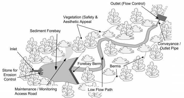
A dry pond is a detention basin designed to temporarily store collected stormwater runoff and release it at a controlled rate through an outlet (MOE, 2003)[1]. Also known as infiltration basins or detention basins (according to their features), dry ponds are a grassed alternative to bioretention cells. Dry ponds may have a deep pool of water in the sediment forebay to reduce scour and resuspension of sediment, but do not have a permanent pool of water in the main basin. This permits the dry pond to be integrated into the landscape and used as an amenity space. Dry ponds are recommended as flood control structures to accommodate occasional excess overflow downstream of other structural BMPs. Compared to wet ponds, dry ponds are less expensive to install, require less maintenance, and may involve less liability for the community (Fairfax County, 2025)[2].
Dry ponds are ideal for:
- Managing infrequent extreme flow events,
- erosion management,
- incorporating into parks and other green recreational spaces, and
- distributing across a larger development site.
Click the button below to read about a case study of a dry pond on the UTSC campus.

STEP Training[edit]
Click the button on the left to register for training on SWM pond inspection and maintenance and the button on the right to learn about wet ponds:


Planning considerations[edit]

Location[edit]
Dry ponds are a useful tool for managing flooding during larger storm events. They are well suited to being placed downstream of other smaller distributed BMPs as an end-of-pipe control for occasional backup flood protection. Where possible, they should be integrated into amenity space, given that users rarely wish to continue outdoor activities during such intense rainstorms.
Infiltration[edit]
For information about constraints to infiltration practices, and approaches and tools for identifying and designing within them see Infiltration. For guidance on infiltration testing and selecting a design infiltration rate see Design infiltration rate.

Public safety[edit]
Where temporary storage of water occurs on the surface, the depth and rate of rise of the water should be sufficiently low that risks are minimized for site users, especially since the temporary nature of the storage facility will mean that the public are not accustomed to its presence. A risk assessment should be undertaken of the frequency and rate of flooding to a range of inundation depths in order that public safety is not jeopardised (Ballard et al., 2015)[6]. Signs should be erected around the dry pond at locations highly visible to the public to identify the site as a stormwater management facility and raise awareness of the function and hazards (City of Toronto, 2015)[5].
Water temperature[edit]
Dry detention ponds can elevate the temperature of stormwater. This effect can be reduced by shortening detention time (US EPA, 2021)[7], increasing canopy cover (LSRCA, 2022)[8], or installing a cooling trench at the pond outlet (City of Toronto, 2015)[5]. Alternative stormwater controls may be better suited for areas that discharge to cold-water streams.
Cold Climates[edit]
Dry ponds, especially those without infiltration, are typically the least affected by winter/spring conditions because there is no large permanent pool. Precautions can be taken to guard against freezing of pipes and orifices, and a by-pass (flow splitter) can be employed to limit inflow during spring freshet (MOE, 2003)[1].
Design[edit]
| Element | Design Objective | Criteria |
|---|---|---|
| Drainage Area | Minimum orifice size (see flow control) |
|
| Treatment Volume | Provision of appropriate level of protection |
|
| Active Storage | Detention |
|
| Forebay | Pre-treatment |
|
| Length-to-Width Ratio | Maximize flow path and minimize short-circuiting potential |
|
| Depth | Safety |
|
| Side slopes (See also berms) | Safety |
|
| Inlet | Avoid clogging/freezing |
|
| Outlet (See also flow control) | Avoid clogging/freezing |
|
| Maintenance access | Access for backhoes or dredging equipment |
|
| Buffer | Safety |
|
Volume[edit]
The surface storage volume of a dry pond (Ap) is determined:

Where:
- RVCT = Runoff volume control target (mm)
- Ac = Area of the catchment (m2)
- f' = design infiltration rate (mm/hr)
- t = time permitted for ponding to infiltrate (hrs) (typically 48 hours)
Detention time[edit]
A minimum detention time of 24 hours should be targeted in all instances, but 48 hours is preferred for water quality benefits. Where this necessitates a very low outflow, a vortex valve or similar is recommended over an orifice or pipe restriction. The detention time is approximated by the drawdown time. The drawdown time in the pond can be estimated using the classic falling head orifice equation which assumes a constant pond surface area (MOE, 2003)[1]. This assumption is generally not valid, and a more accurate estimation can be made if the equation is solved as a differential equation. This is easily done if the relationship between pond surface area and pond depth is approximated using a linear regression:

Where
- t = Drawdown time (s)
- Ap = Surface area of the pond(m2)
- C = Discharge coefficient (typically 0.63)
- Ao = Cross-sectional area of the orifice(m2)
- g = Gravitational acceleration constant (9.81 m/s2)
- h1 = Starting water elevation above the orifice (m)
- h2 = Ending water elevation above the orifice (m)
C2 slope coefficient from the area-depth linear regression C3 intercept from the area-depth linear regression
Settling Velocity of Particulates[edit]
The process of sedimentation is enacted when solids "settle" to the bottom of a sedimentation practice, from suspension in moving or retained water (in this case a dry pond BMP). Due to dry ponds having grassy channels and slopes they are able to over time decrease the velocity of incoming stormwater flow that enters the practice. This combined with the agility of the practice to allow for temporary storage and ponding of water (24 - 48 hr) allows excess sediments (sand, silts, clay and small aggregates) and associated pollutants to settle and be retained within the BMP (Weiss et al. 2010)[9]. These sediments should be removed periodically to maintain as designed performance of the feature. The following calculations are for measuring the settling velocities of various solids.
Stoke's Law for settling solids[edit]
Stoke's Law measures solids settling in stormwater features and is applicable to fines, clay, silt, and sand in water.

Where
- V = settling velocity of particles (m/s)
- g = gravitational acceleration constant (9.81 m/s2)
- d = diameter of the solid (spherical) (m)
- ρ1 = mass density of solid (kg/m3)
- ρ: mass density of water (1000 kg/m3)
- v: kinematic viscosity of water at (1 mm2/s)
Ferguson & Church (2004)[10][edit]
Ferguson & Church's calculation meanwhile allows for designers to include the relationship between settling velocity and particle diameter size. A relationship for settling velocity that incorporates larger particles, such as sands with Reynolds Number (RE) > 10. The equation becomes Stokes' Law when particles have smaller diameters and allows for a constant drag coefficient to be applied for larger particle diameters.

Where
- V = settling velocity of particles (m/s)
- g = gravitational acceleration constant (9.81 m/s2)
- d = diameter of the solid (spherical) (µm)
- v = kinematic viscosity of water (1 mm2/s)
- R = Specific gravity for solid in question (i.e. 1.58kg/cm3 for sand)
- C = Typical constant for spherical solids (0.4) and (1.0) for sand grains
See the table below for average settling velocities of different particle size ranges and particle types based on MOEE (1994)[11] and from Muschalla, 2014[12]
Size Fraction (i) |
Particle size range (µm) |
Average settling velocity of particles in size fraction i, Vsi (m/s) |
Fraction of total mass contained in size fraction i (%) - MOEE |
Fraction of total mass contained in size fraction i (%) - measured |
|---|---|---|---|---|
| 1 | x ≤ 20 | 2.54E-06 | 20 | 83.4 |
| 2 | 20 ≤ x ≤ 40 | 1.30E-05 | 10 | 9.1 |
| 3 | 40 ≤ x ≤ 60 | 2.54E-05 | 10 | 4.4 |
| 4 | 60 ≤ x ≤ 130 | 1.27E-04 | 20 | 4.1 |
| 5 | 130 ≤ x ≤ 400 | 5.93E-04 | 20 | - |
| 6 | 400 ≤ x ≤ 4000 | 5.50E-03 | 20 | - |
Forebay[edit]

A sediment forebay facilitates maintenance and improves pollutant removal by trapping larger particles near the inlet of the pond. The forebay should be separated from the main pond by an earthen berm, which should be constructed as a small dam since the downstream portion of the pond remains dry. A weir at the top of the berm will convey flows to the downstream section during storm events. To facilitate maintenance, a pipe with an upstream valve should be installed within the berm to allow the forebay to be drawn down for cleaning (MOE, 2003)[1].
The berm should be planted with emergent vegetation to enhance filtration of water as it passes over. Refer to Wetlands: Plants for a list of Ontario native emergent plants.
Inlet[edit]

The number of inlets into the pond should be minimized. The invert of the inlet pipe is set at the maximum design water level in the pond. To reduce erosion risk, the use of environmental stone or interlocking blocks with large openings that support vegetative growth is recommended at the inlet. A flow deflector or energy dissipation blocks may also be installed to limit scour and prevent the resuspension of previously settled pollutants from the pond bottom (MOE, 2003)[1].
Outlet[edit]

The outlet should be located in the pond embankment wherever possible for ease of maintenance and aesthetics. The performance of a dry pond can be enhanced via a shallow micropool at the outlet which concentrates finer sediment and reduces re-suspension. The micropool is normally planted with hardy wetland species such as cattail (MOE, 2003)[1]. A reverse sloped pipe makes the outlet more resilient to clogging (MOE, 2003)[1].
For excess flow control, see Flow through riser
- https://www.fhwa.dot.gov/engineering/hydraulics/software/hy8/
- https://www.hydrologystudio.com/no-fail-detention-pond-design/
Buffer[edit]
A minimum of a 3 m buffer strip from the maximum design water level mark should be installed to meet safety (e.g., restrict access to steep areas or inlet/outlet locations), wind screening, shading, aesthetic, and public amenity objectives. When possible,
- at least least 5 species should be planted in a random pattern to prevent the establishment of monoculture areas,
- a large number of young plant stocks, tree whips and seedlings should be planted along with a small number of large mature shrubs and trees, and
- a naturalized landscape approach should be used which strives for a vegetation community with long-term sustainability and no maintenance requirements (MOE, 2003)[1].
See Salt-Tolerant Turf Grasses, Shrubs: List, and Trees: List for a list of native species which could be planted in the buffer strip.
Planting Strategy[edit]
Depending upon the proposed planting strategy, these maximum storage depths may be reduced to 1 to 1.5 metres. It is anticipated, however, that the dry pond will not be actively planted in the extended detention portion due to harsh growing conditions (frequent wetting/drying). The planting approach for a dry pond is typically less intensive than for a wet pond, involving fewer species and lower planting density. Vegetation is generally organized into three zones according to soil moisture conditions:
- Extended detention area
- Flood fringe area (for combined quality/quantity SWMPs)
- Upland area
Growing conditions in the extended detention area of a dry pond are more challenging than in a wet pond because there is no permanent pool to moderate moisture levels. As a result, this zone requires particular attention to ensure that desired plant species establish successfully (MOE, 2003)[1].
Performance[edit]
| Imperviousness of Catchment | Storage Volume (m³/ha) | Permanent pool (extended detention) (m³/ha) |
|---|---|---|
| 35% | 90 | 50 |
| 55% | 150 | 81 |
| 70% | 200 | 89 |
| 85% | 240 | 107 |
Stormwater ponds and constructed wetlands are designed to meet water quality targets based on drainage area imperviousness. Pollutant removal occurs mainly in the permanent pool, with effectiveness depending on hydraulic residence time—longer times improve sedimentation and biological uptake. In Ontario, most facilities must achieve 80% TSS removal, with storage requirements based on a 24-hour drawdown time (MOE, 2003)[1].
Dry ponds may include a deep pool in the sediment forebay to minimize scour and sediment resuspension, but the main basin does not retain a permanent pool of water. As a result, contaminants cannot settle between storm events, nor is there dilution of pollutants during storms. Consequently, while dry ponds are effective for erosion and flood control, they may need to be paired with other LID features in a treatment train to improve water quality beyond the basic treatment level of 60% long-term TSS removal (MOE, 2003)[1].
Modeling[edit]


The Low Impact Development Treatment Train Tool can analyze annual and event-based runoff volumes and pollutant load removal for dry ponds.
![]()
| Stage Storage | |
|---|---|
| Name | Important to have a unique name, to connect it with the catchment area |
| Storage type | Dry detention ponds |
| Bottom elevation (m) | This is important to correspond with other components, e.g. when the overflow is coupled to another BMP within a treatment train |
| Maximum depth (m) | |
| Lined/unlined | Unlined (ideally) |
| Underlying soil | Choose from five; sandy soils drain more quickly. |
| Evaporation factor | ? |
| Suction head (mm) | ? |
| Saturated conductivity (mm/hr) | ? |
| Initial soil moisture deficit (fraction) | ? |
| Curves | |
| The Curves table is designed to accommodate the side slopes. The top line begins at 0 m, with subsequent depths in the following lines. | |

Inspection and Maintenance[edit]

Inspection points for dry ponds include (MOE, 2003)[1]:
- standing water in pond after rain events for longer than designed detention time - may indicate outlet blockage
- pond is always/relatively dry, even throughout designed detention time - may indicate inlet blockage
- vegetation around the pond unhealthy or dying - may indicate poor species selection
- visible sediment accumulation in the bottom of the pond or around the high water line of the pond - may indicate need for sediment removal
A field data sheet for the inspection of constructed wetlands is available below. You can download (downward facing arrow on the top righthand side) and print (Printer emoticon on top right hand side) the the Pond/Wetland Maintenance and Inspection Form developed by Toronto and Region Conservation Authority (TRCA) and CH2M Hill Canada.
Maintenance requirements vary between dry ponds and wet ponds, although many maintenance tasks overlap.
| Maintenance Activity | Dry Pond | Wet Pond |
|---|---|---|
| Inspection | ✓ | ✓ |
| Grass cutting | ✓ | ✓ |
| Weed control | ✓ | ✓ |
| Removal of accumulated sediments | ✓ | ✓ |
| Upland vegetation replanting | ✓ | ✓ |
| Trash removal | ✓ | ✓ |
| Outlet valve adjustment | ✓ | ✓ |
| Shoreline fringe and flood fringe vegetation replanting | ✓ | |
| Aquatic vegetation replanting | ✓ |
Forecasting Sediment Accumulation and Cleanouts[edit]
| Catchment Imperviousness | Sediment Accumulation (m³/ha) |
|---|---|
| 35% | 40 |
| 55% | 69 |
| 70% | 111 |
| 85% | 133 |
Accurate forecasting of sediment accumulation in stormwater facilities helps managers schedule and budget for maintenance. MOE (2003) recommends SWMFs be cleaned when the TSS removal efficiency declines below 5% of its original design criterion[1]. For example, if a dry pond is designed to remove 60% of TSS, an efficiency reduction to 55% triggers the need for sediment removal. The rate of sediment accumulation differs for each facility, and depends on factors such as the characteristics of drainage area (e.g., land use; level of imperviousness; upstream construction activities and effectiveness of sediment and erosion control practices) and municipal practices (e.g. frequency of road/catchbasin cleaning, sanding/salting practices).
To assess whether a SWMF needs sediment removal, three factors are required:
- Current storage capacity (from sediment depth measurements or TSS load modelling).
- Minimum efficiency allowed (5% reduction, per MOE 2003).
- The facility’s efficiency–storage relationship, to compare storage loss with the 5% efficiency threshold.
STEP's Inspection and Maintenance Guide for Stormwater Management Ponds and Constructed Wetlands (section 4.5.1: Forecasting Based on Sediment Depth Measurements) describe methods for forecasting the need for sediment removal and provides a sample forecasting exercise.
Gallery[edit]
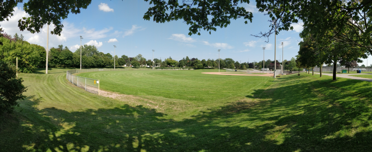
Wishing well park is a baseball field with flood warning signs, Scarborough ON
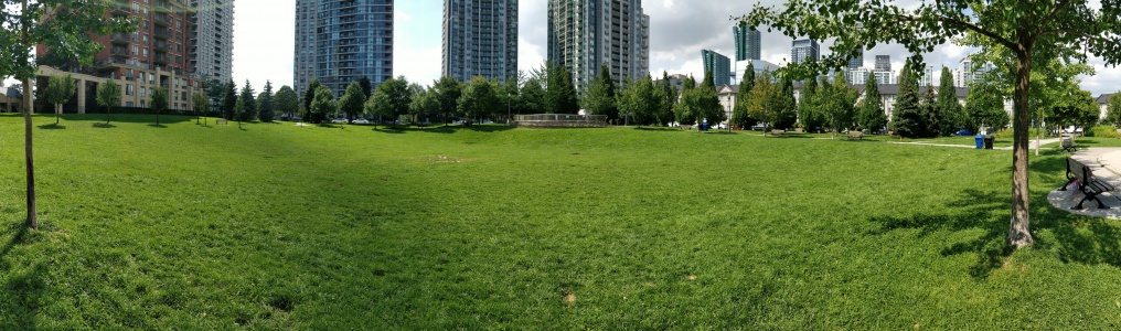
Avondale Park, designed for flood storage, but not optimized for infiltration, North York ON
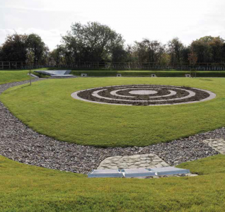
A multi-functional dry basin, still due to be fitted with playground equipment. Cambridge, UK. Photo credit: Simon Bunn

Stormwater lagoon, Wilmhurst Road, Warwick. UK. Photo credit: Robin Stott

Dry polder northwest of Vincencov, Prostějov. Czech Republic. Photo credit: Jiří Komárek


External links[edit]
References[edit]
- ↑ 1.00 1.01 1.02 1.03 1.04 1.05 1.06 1.07 1.08 1.09 1.10 1.11 1.12 1.13 1.14 1.15 1.16 1.17 1.18 1.19 Ontario Ministry of Environment. 2003. Stormwater Management Planning and Design Manual. https://www.ontario.ca/document/stormwater-management-planning-and-design-manual/stormwater-management-plan-and-swmp-design
- ↑ Fairfax County. 2025. Understanding Stormwater Ponds: Wet Ponds, Dry Ponds and Stormwater Pond Retrofits. https://www.fairfaxcounty.gov/soil-water-conservation/understanding-stormwater-ponds
- ↑ Dennich, C. & Eves, C. 2024. KDO3 Dry Pond Sub-surface Infiltration Facility Design, Construction & Monitoring. Source to Stream Conference Presentation. https://sourcetostream.com/2024-track-1-day-1-denich-eves/
- ↑ TD & H Engineering. 2025. UPGF Storm Water Detention Pond. https://tdhengineering.com/project/upgf-multiuse-athletic-field-intermittent-storm-water-detention-pond/
- ↑ 5.0 5.1 5.2 City of Toronto. 2015. Landscape Design Guidelines for Stormwater Management Ponds. https://www.toronto.ca/wp-content/uploads/2017/11/913f-ecs-specs-landscape-Landscape_Design_Guidelines_SWM_Ponds_Sep2015.pdf
- ↑ 6.0 6.1 Ballard, B. W., Wilson, S., Udale-Clarke, H., Illman, S., Scott, T., Ashley, R., & Kellagher, R. 2015. The SuDS Manual. London.https://www.scotsnet.org.uk/__data/assets/pdf_file/0023/51764/CIRIA-report-C753-the-SuDS-manual-v6.pdf
- ↑ United States EPA. 2021. Stormwater Best Management Practice. https://www.epa.gov/system/files/documents/2021-11/bmp-dry-detention-ponds.pdf
- ↑ Lake Simcoe Region Conservation Authority. 2022. Technical Guidelines for Stormwater Management Submissions. https://www.lsrca.on.ca/wp-content/uploads/2023/06/Technical-Guidelines-for-Stormwater-Management-Submissions.pdf
- ↑ Gulliver, J.S., A.J. Erickson, and P.T. Weiss (editors). 2010. "Stormwater Treatment: Assessment and Maintenance. University of Minnesota, St. Anthony Falls Laboratory. Minneapolis, MN. https://stormwaterbook.safl.umn.edu/
- ↑ Ferguson, R.I. and Church, M. 2004. A simple universal equation for grain settling velocity. Journal of sedimentary Research, 74(6), pp.933-937. for settling solids. http://geoweb.uwyo.edu/geol5330/FergusonChurch_GrainSettling_JSR04.pdf
- ↑ MOEE (1994). Stormwater management practices planning and design manual. Ministry of Environment and Energy, Ontario, Canada.
- ↑ Muschalla, D., Vallet, B., Anctil, F., Lessard, P., Pelletier, G. and Vanrolleghem, P.A., 2014. Ecohydraulic-driven real-time control of stormwater basins. Journal of hydrology, 511, pp.82-91.
- ↑ https://sustainabletechnologies.ca/lid-lcct
- ↑ City of Airdrie. 2024. Airdrie dry pond maintenance extended till next month. https://discoverairdrie.com/articles/airdrie-dry-pondmaintenance-extended-till-next-month
- ↑ STEP. 2016. Inspection and maintenance guide for stormwater management ponds and constructed wetlands. https://sustainabletechnologies.ca/app/uploads/2018/04/SWMFG2016_Guide_April-2018.pdf