Gravel diaphragms
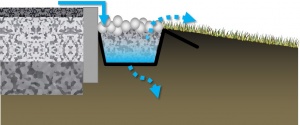
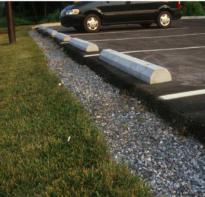
Gravel diaphragms are simply gravel filled trenches which act as inlet structures by redistributing concentrated flow to sheet flow: reducing the erosive power of the water and promoting infiltration. They also act as a pretreatment by settling out sediment particles before they reach any downstream structure or practice.
If the contributing drainage area is solely turf (e.g., sports field), then the gravel diaphragms may be eliminated from the treatment train.
Gravel diaphragms are ideal for distributing flow and providing pretreatment for
Planning[edit]
The gravel diaphragm serves two purposes. First, it acts as a pretreatment device, settling out coarse particles before they reach an infiltration practice. Second, it acts as a level spreader, maintaining sheet flow as runoff flows over the filter strip. If the contributing drainage area is steep, then larger stone should be used in the diaphragm,
- Diaphragms can be designed along curves as readily as straight lines,
- As they are not a conveyance practice, they should be designed along a single contour line, promoting the level spreading function,
- Flow should be directed into the device laterally.
Design[edit]
- Where flow comes off an impervious surface, an elevation drop of 75 to 150 mm to the surface of the diaphragm is recommended to dissipate energy, promote settling and allow for accumulation of sediment and debris between cleanings;
- Typical dimensions for the trench excavation are 300 mm deep and 600 mm wide. The trench may be any length;
- The trench should be lined with geotextile before filling with gravel; and,
- River rock or decorative stone may be included in a layer at the top of the gravel fill, for aesthetic value.
Materials[edit]
Gravel[edit]
The type of medium sized aggregates recommended for gravel diaphragms are described in choker layer. In some contexts it may be desirable to apply a surface layer of more decorative stone.
Geotextiles[edit]
See Clogging for notes on their application in LID structures.
Geotextiles can be used to prevent downward migration of smaller particles in to larger aggregates, and slump of heavier particles into finer underlying courses. Geotextiles are commonly used on low strength soils (CBR<4). The formation of biofilm on geotextiles has also been shown to improve water quality:
- By degrading petroleum hydrocarbons[1]
- By reducing organic pollutant and nutrient concentrations [2]
- When installing geotextiles an overlap of 150 - 300 mm should be used.
Material specifications should conform to OPSS 1860 for Class II geotextile fabrics [3]. Note when expansive clays are present, a non-infiltrating design may be necessary. If used, geotextile socks around perforated pipes should conform to ASTM D6707 with minimum water flow rate conforming to ASTM D4491 (12,263 L/min/m2 at 5 cm head).
- Fabrics should be woven monofilament or non-woven needle punched.
- Woven slit film and non-woven heat bonded fabrics should not be used, as they are prone to clogging.
In choosing a product, consider:
- The maximum forces that will be exerted on the fabric (i.e., what tensile, tear and puncture strength ratings are required?),
- The load bearing ratio of the underlying native soil (i.e. is the geotextile needed to prevent downward migration of aggregate into the native soil?),
- The texture (i.e., grain size distribution) of the overlying and underlying materials, and
- The suitable apparent opening size (AOS) for non-woven fabrics, or percent open area (POA) for woven fabrics, to maintain water flow even with sediment and microbial film build-up.
| Percent soil/filter media passing 0.075 mm (#200 sieve) | Non-woven fabric apparent opening size (AOS, mm) | Woven fabric percent open area (POA, %) | Permittivity (sec-1) |
|---|---|---|---|
| >85 | ≤ 0.3 | - | 0.1 |
| 50 - 85 | ≤ 0.3 | ≥ 4 | 0.1 |
| 15 - 50 | ≤ 0.6 | ≥ 4 | 0.2 |
| 5 - 15 | ≤ 0.6 | ≥ 4 | 0.5 |
| ≤ 5 | ≤ 0.6 | ≥ 10 | 0.5 |
Performance research[edit]
http://www.mdpi.com/2073-4441/7/4/1595/htm
External Resources[edit]
- VIRGINIA DCR STORMWATER DESIGN SPECIFICATION No. 2
- National Engineering Handbook Part 628 Dams Chapter 45 Filter Diaphragms
References[edit]
- ↑ Newman AP, Coupe SJ, Spicer GE, Lynch D, Robinson K. MAINTENANCE OF OIL-DEGRADING PERMEABLE PAVEMENTS: MICROBES, NUTRIENTS AND LONG-TERM WATER QUALITY PROVISION. https://www.icpi.org/sites/default/files/techpapers/1309.pdf. Accessed July 17, 2017.
- ↑ Paul P, Tota-Maharaj K. Laboratory Studies on Granular Filters and Their Relationship to Geotextiles for Stormwater Pollutant Reduction. Water. 2015;7(4):1595-1609. doi:10.3390/w7041595.
- ↑ ONTARIO PROVINCIAL STANDARD SPECIFICATION METRIC OPSS 1860 MATERIAL SPECIFICATION FOR GEOTEXTILES. 2012. http://www.raqsb.mto.gov.on.ca/techpubs/OPS.nsf/0/2ccb9847eb6c56738525808200628de1/$FILE/OPSS%201860%20Apr12.pdf. Accessed July 17, 2017


