Difference between revisions of "Bioretention"
Jenny Hill (talk | contribs) (→Design) |
Jenny Hill (talk | contribs) (→Design) |
||
| Line 72: | Line 72: | ||
<li>The applicable infiltration coefficient (q) is calculated by applying the safety factor to the [[Infiltration testing|measured infiltration rate]].</li> | <li>The applicable infiltration coefficient (q) is calculated by applying the safety factor to the [[Infiltration testing|measured infiltration rate]].</li> | ||
<li>Determine the drainage catchment area (A<sub>D</sub>), and outline the location of the bioretention facility. To begin with, budget for at least 10% of the contributing impervious area to be required for the BMP. </li></li> | <li>Determine the drainage catchment area (A<sub>D</sub>), and outline the location of the bioretention facility. To begin with, budget for at least 10% of the contributing impervious area to be required for the BMP. </li></li> | ||
| − | <li>Unless the biomedia fill material has been tested and certified otherwise, a porosity value (V<sub>r</sub>) of 0. | + | <li>Unless the biomedia fill material has been tested and certified otherwise, a porosity value (V<sub>r</sub>) of 0.35 may be assumed (i.e. void ratio 35%). </li> |
<li>Bioretention facilities are usually between 0.5 m and 1.25 m deep, owing to construction considerations. Determine the maximum available depth (c<sub>c max</sub>) from the site constraints. The [[Infiltration]] page has some of these listed. </li> | <li>Bioretention facilities are usually between 0.5 m and 1.25 m deep, owing to construction considerations. Determine the maximum available depth (c<sub>c max</sub>) from the site constraints. The [[Infiltration]] page has some of these listed. </li> | ||
<li>Identify the duration (D) and intensity (i) of design storm(s). </li></ul> | <li>Identify the duration (D) and intensity (i) of design storm(s). </li></ul> | ||
<li>Calculate the required area</li> | <li>Calculate the required area</li> | ||
| − | [[Media:Infiltration | + | [[Media:Infiltration Sizing.xlsx|Sunflowers]] |
</ol> | </ol> | ||
Revision as of 16:20, 4 July 2017
This article is about planted installations designed to capture surface runoff through an engineered soil with subterranean infrastructure.
For simpler, residential systems, see Rain gardens.
For linear systems, which convey flow, but are otherwise similar see Bioswales.
Overview[edit]
Bioretention cells are one of the most well recognized form of Low Impact Development. They can encompass all mechanisms of action: infiltration, filtration and evapotranspiration.
Bioretention cells are an ideal technology for:
- Fitting functional vegetation into urban landscapes
- Treating runoff collected from nearby impervious surfaces
The fundamental components of a bioretention cell are:
- Biomedia: An engineered soil mix
- Planting
- Storage layer of coarse aggregate
- Under-drain to redistribute or remove excess water
- Impermeable membrane to prevent infiltration to soils below
<panelSuccess>
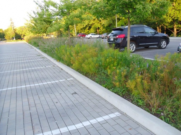
These bioretention cells at Edwards Gardens in Toronto receive inflow from hydraulically connected permeable paving.

</panelSuccess>
Design for maintenance
Will the BMP be a snow storage facility in winter months?
<panelSuccess>
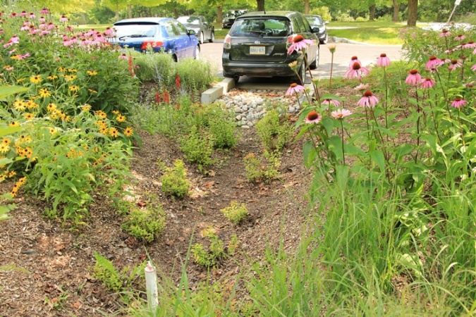
Bioretention cell capturing and treating runoff from adjacent parking lot at the Kortright Centre, Vaughan.

</panelSuccess>
Design[edit]
Sizing
- Gather input data:
- The applicable infiltration coefficient (q) is calculated by applying the safety factor to the measured infiltration rate.
- Determine the drainage catchment area (AD), and outline the location of the bioretention facility. To begin with, budget for at least 10% of the contributing impervious area to be required for the BMP.
- Unless the biomedia fill material has been tested and certified otherwise, a porosity value (Vr) of 0.35 may be assumed (i.e. void ratio 35%).
- Bioretention facilities are usually between 0.5 m and 1.25 m deep, owing to construction considerations. Determine the maximum available depth (cc max) from the site constraints. The Infiltration page has some of these listed.
- Identify the duration (D) and intensity (i) of design storm(s).
- Calculate the required area Sunflowers
Underdrain
This is a collection of three articles with the common theme of being aggregate products for various applications in LID.
Underground construction aggregates[edit]
For reservoirs[edit]
This article gives recommendations for aggregate to be used to store water for infiltration. This is usually called 'clear stone' at aggregate yards.
To see an analysis of Ontario Standard Specifications for granular materials, see OPSS aggregates.
For advice on decorative surface aggregates see Stone
Gravel used for underdrains in bioretention, infiltration trenches and chambers, and exfiltration trenches should be 20 or 50 mm, uniformly-graded, clean (maximum wash loss of 0.5%), crushed angular stone that has a porosity of 0.4[1].
The clean wash to prevent rapid accumulation of fines from the aggregate particles in the base of the reservoir. The uniform grading and the angularity are important to maintain pore throats and clear voids between particles. (i.e. achieve the porosity). Porosity and permeability are directly influenced by the size, gradation and angularity of the particles [2]. See jar test for on-site verification testing protocols.
Gravel with structural requirements should also meet the following criteria:
- Minimum durability index of 35
- Maximum abrasion of 10% for 100 revolutions and maximum of 50% for 500 revolutions
Standard specifications for the gradation of aggregates are maintained by ASTM D2940
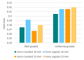
The highest porosity is found in uniformly graded aggregate, as there are no smaller particles to occupy the inter-particle pores. [2]
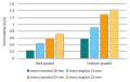
Higher permeability is found in larger, angular, uniformly graded aggregate. This is due to larger pore sizes and lower tortuosity. [2]


For choking/choker layers[edit]

In bioretention systems a choker layer of ≥ 100 mm depth is the recommended method to prevent migration of finer filter media into the underlying storage reservoir aggregate. These same mid-sized granular materials are recommended for use in Stormwater planter underdrains and may be useful in the fine grading of foundations courses for permeable pavements.
Suitable materials include:
- High performance bedding (HPB)
- Clean, angular aggregate screened to between 6 and 10 mm. Widely available and designed specifically for drainage applications. Free from fines by definition.
- HL 6
- Is a clean, angular aggregate screened between 10 and 20 mm. Free from fines by definition.
- Pea Gravel
- Rounded natural aggregate, screened between 5 and 15 mm, and washed free from fines.
In most scenarios, a geotextile layer is unnecessary and has been associated with rapid decline and clogging in some circumstances.
OPS Aggregates[edit]
Of the standard granular materials in the standard OPSS.PROV 1010 only Granular O is recommended as a substitute for clear stone in LID construction.
Where Granular O is substituted for clear stone in underground reservoir structures, the porosity used in design calculations shall be 0.3 unless laboratory testing proves otherwise.
Examples of BMPs with underground reservoirs include Underdrains, infiltration trenches, permeable pavements, infiltration chambers, exfiltration trenches.
All other mixes must be avoided for free drainage or storage as they are permitted to contain a higher enough proportion of fines to reduce permeability below 50 mm/hr.
For more information see OPS aggregates
Landscaping aggregates[edit]


For advice on aggregates used in underdrains, see Reservoir aggregate.
Stone or gravel can serve as a low maintenance decorative feature, but it may also serve many practical functions on the surface of an LID practice.
Stone for erosion control[edit]
Aggregates used to line swales or otherwise dissipate energy (e.g. in forebays) should have high angularity to increase the permissible shear stress applied by the flow of water. [3] However, in some surface landscaped applications there may be a desire to use a rounded aggregate such as 'river rock' for aesthetic reasons. Rounded stones should be of sufficient size to resist being moved by the flow of water. Typical stone for this purpose ranges between 50 mm and 250 mm in diameter. The larger the stone, the more energy dissipation.
- Stone beds should be twice as thick as the largest stone's diameter.
- If the stone bed is underlain by a drainage geotextile, annual inspection and possible replacement should be performed as there is a potential for clogging of this layer to occur.
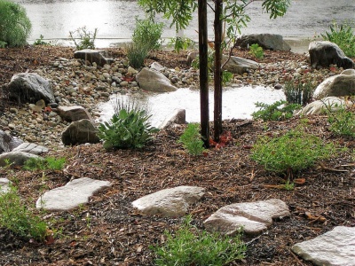
Stone lining the ponding zone of this rain garden. Image credit California Native Plant Society

Coarse angular stone laid onto a geogrid and geotextile. Image from wikimedia commons


Stone mulch[edit]
Finer inorganic mulch materials can be of value applied in areas with extended ponding times i.e. in the the centre of recessed, bowl shaped bioretention, stormwater planters, trenches or swale practices. Inorganic mulches resist movement from flowing water and do not float. Applying a thin layer of inorganic mulch over the top of wood based mulch has been shown to reduce migration of the underlying layer by around 25% [4]. Inorganic mulches which may be available locally, include:
- Pea gravel
- River rock/beach stone
- Recycled glass
- Crushed mussel shells
On-site verification[edit]

Specifying that aggregates for the construction of LID practices must be free from fines is important. But checking that the delivered materials meet specification is essential to reduce problems with construction and longer term performance.
When possible, Construction Managers should observe the offloading of materials to watch for dust clouds. Aggregates or sand for LID construction should not give rise to clouds of dust when dumped.
A simple jar test can be used to gauge the proportion of fines in an aggregate product before acceptance.
Apparatus:
- A large wide-mouthed jar - glass or clear plastic are both fine,
- Tap water, and
- The aggregate to be tested.
Method:
- Collect approximately 5 cm of material in the jar (or at least two complete layers of 50 mm clear stone),
- Add water to around 3/4 full,
- Secure cap and shake,
- Leave for at least 30 minutes and until the water is clear - plan to run the test overnight when possible,
- Examine the layer of sediment - if > 3 mm has been washed from 5 cm of product, the material should be rejected,
Note that the sediment may collect on top of, or at the bottom of the construction material.
External references[edit]
- Heger, S. (2014). Critical Aspects During System Installation and Inspection General equipment considerations. In PMSA conference. Retrieved from http://www.psma.net/pdf/14/conference-presentations/Keys_to_Installation_(Heger).pdf
- Manitoba. (2010). Onsite Wastewater Management Systems: Field Reference Guide - JAR TEST. Retrieved from http://www.gov.mb.ca/sd/envprograms/wastewater/pdf/jar_test_reference_03_2010.pdf

Perforated pipes are a common component of underdrains used in bioretention, permeable pavements, infiltration trenches and exfiltration systems.
Pipes should be manufactured in conformity with the latest standards by the Canadian Standards Association (CSA) or ASTM International.
- Perforated pipes should be continuously perforated, smooth interior HDPE or PVC.
- Wherever possible pipes should be ≥200 mm internal diameter to reduce potential of freezing and to facilitate push camera inspections and cleaning with jet nozzle equipment.
- Smooth interior facilitates inspection and maintenance activities; internal corrugations can cause cameras or hydrojetting apparatus to become snagged.
- A perforated pipe with many rectangular slots has better drainage characteristics than a pipe with similar open area provided by fewer circular holes [5].
- Non-perforated pipes should be used for conveyance of stormwater to and from the facility, including overflow. It is good practice to extend the solid pipe approximately 300 mm within the reservoir or practice to reduce the potential for native soil migration into the pipe.
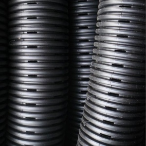
Pipe with slotted perforations
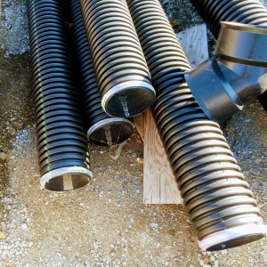
Perforated pipes awaiting installation, note the 45 degree couplings used to facilitate push camera inspection and jet nozzle cleaning.


See also: Flow through perforated pipe
Geotextile Membrane

See Clogging for notes on their application in LID structures.
Geotextiles can be used to prevent downward migration of smaller particles in to larger aggregates, and slump of heavier particles into finer underlying courses. Geotextiles are commonly used on low strength soils (CBR<4). The formation of biofilm on geotextiles has also been shown to improve water quality:
- By degrading petroleum hydrocarbons[6]
- By reducing organic pollutant and nutrient concentrations [7]
- When installing geotextiles an overlap of 150 - 300 mm should be used.
Material specifications should conform to OPSS 1860 for Class II geotextile fabrics [8]. Note when expansive clays are present, a non-infiltrating design may be necessary. If used, geotextile socks around perforated pipes should conform to ASTM D6707 with minimum water flow rate conforming to ASTM D4491 (12,263 L/min/m2 at 5 cm head).
- Fabrics should be woven monofilament or non-woven needle punched.
- Woven slit film and non-woven heat bonded fabrics should not be used, as they are prone to clogging.
In choosing a product, consider:
- The maximum forces that will be exerted on the fabric (i.e., what tensile, tear and puncture strength ratings are required?),
- The load bearing ratio of the underlying native soil (i.e. is the geotextile needed to prevent downward migration of aggregate into the native soil?),
- The texture (i.e., grain size distribution) of the overlying and underlying materials, and
- The suitable apparent opening size (AOS) for non-woven fabrics, or percent open area (POA) for woven fabrics, to maintain water flow even with sediment and microbial film build-up.
| Percent soil/filter media passing 0.075 mm (#200 sieve) | Non-woven fabric apparent opening size (AOS, mm) | Woven fabric percent open area (POA, %) | Permittivity (sec-1) |
|---|---|---|---|
| >85 | ≤ 0.3 | - | 0.1 |
| 50 - 85 | ≤ 0.3 | ≥ 4 | 0.1 |
| 15 - 50 | ≤ 0.6 | ≥ 4 | 0.2 |
| 5 - 15 | ≤ 0.6 | ≥ 4 | 0.5 |
| ≤ 5 | ≤ 0.6 | ≥ 10 | 0.5 |
Performance research[edit]
http://www.mdpi.com/2073-4441/7/4/1595/htm
Biomedia


It is recommended that the mixture comprises:
| Blend A: Drainage rate priority | Blend B: Water quality treatment priority | |
|---|---|---|
| Application | Impervious area to pervious area (I:P) ratio of 15:1 or greater |
|
| Proportions |
3 parts sand |
3 parts sand |
| Porosity | This mixture may be assumed to have a porosity of 0.4 unless demonstrated otherwise | This mixture may be assumed to have a porosity of 0.35 unless demonstrated otherwise |
Filter media should be obtained premixed from the vendor and meet all municipal, provincial and federal environmental standards. To minimize transportation-related environmental impacts, filter media should be obtained from local vendors and blended from locally sourced materials. Topsoil used to produce the mix should be passed through a 5 centimetre (2 inch) screen to remove large rocks, roots and other debris, while retaining soil peds. Samples of the filter media should be dried, ground and tested by a certified soil testing laboratory to ensure they meet the following specifications:
| Characteristic | Criterion | Recommended test method |
|---|---|---|
| Particle-size distribution (PSD) | < 25% silt- and clay-sized particles (smaller than 0.05 mm) combined; 3 to 12% clay-sized particles (0.002 mm or smaller) |
ASTM D6913/D6913M, Standard Test Methods for Particle-Size Distribution (Gradation) of Soils Using Sieve Analysis (pebble to sand fraction); and ASTM D7928, Standard Test Method for Particle-Size Distribution (Gradation) of Fine-Grained Soils Using the Sedimentation (Hydrometer) Analysis (silt and clay fraction). |
| Organic matter (OM) | 3 to 10% by dry weight | ASTM F1647, Standard Test Methods for Organic Matter Content of Athletic Field Rootzone Mixes. |
| Phosphorus, plant-available or extractable | 12 to 40 ppm | As measured by the 'Olsen' method for alkaline and calcareous soils (common in Ontario). Alternatives include 'Mehlich I or III', or 'Bray', which is better suited to acidic to slightly alkaline and non-calcareous soils. NB: Results from different test methods are not directly comparable.[9] |
| Cationic exchange capacity (CEC) | > 10 meq/100 g | ASTM D7503, Standard Test Methods for Measuring the Exchange Complex and Cation Exchange Capacity of Inorganic Fine-Grained Soils. |
| Hydraulic conductivity, saturated (Kf) | > 75 mm/h; Blend A > 25 mm/h; Blend B < 300 mm/h; Blend A and B |
ASTM D2434, Standard Test Method for Permeability of Granular Soils (Constant Head), when the sample is compacted to 85% of its maximum dry density in accordance with ASTM D698, Standard Test Methods for Laboratory Compaction Characteristics of Soil Using Standard Effort. |
Note that you may choose not to use particle-size distribution as a criterion for acceptance of a filter media blend, but saturated hydraulic conductivity should be one. While information on particle-size distribution and soil texture are useful in selecting plants, the disconnect between hydraulic conductivity and uniformity of gradation makes it far less important than measuring the saturated hydraulic conductivity directly[10]
Sand[edit]

- Coarse sand for LID construction shall be washed clean and free of toxic materials.
- The pH of the sand shall be ≤ 7.0.
- The coarse sand shall have a fineness modulus index between 2.8 and 3.1 according to ASTM C33/C33M, or otherwise meet the gradation below.
| Sieve | Percent passing |
|---|---|
| 9.5 mm | 100 |
| 4.75 mm (No.4) | 95 - 100 |
| 2.36 mm (No.8) | 80 - 100 |
| 1.18 mm (No.16) | 50 - 85 |
| 0.60 mm (No.30) | 25 - 50 |
| 0.30 mm (No.50) | 5 - 30 |
| 0.15 mm (No.100) | 0 - 10 |
| 0.075 mm (No.200) | ≤ 3 |
Topsoil[edit]
- Topsoil may be material that was stripped from the project site and stored in stockpiles for re-use, or material imported to the site from a supplier provided the physical and chemical characteristics are within acceptable ranges.
- Topsoil shall be in compliance with Ontario Regulation 153/04 Record of Site Condition standards for soil quality or as amended through Ontario Management of Excess Soil - A Guide for Best Management Practices.
- Soil laboratory reports shall certify the material to be suitable for re-use on residential, parkland, institutional, industrial, commercial, or community landscapes for the germination of seeds and the support of vegetative growth.
The factors to consider in determining if a topsoil is suitable for use as planting soil for a vegetated stormwater practice, or use in producing a bioretention filter media mixture include the following:
- Must be friable and capable of sustaining vigorous plant growth;
- Must be free from toxic material and roots, stones or debris over 50 mm (2") in diameter;
- Should not have been passed through sieves or screens smaller than 50 mm (2”) to avoid eliminating peds;
- Should have a Loamy Sand, Sandy Loam, Sandy Clay Loam, Loam or Silty Loam soil texture;
- For use as planting soil for a vegetated stormwater practice , the topsoil must contain a minimum of 5% organic matter by dry weight or be amended so, through addition of an organic soil conditioner;
- For use in producing bioretention filter media Blend B (water quality treatment priority), the topsoil must contain at least 9%, and not greater than 36% clay-sized particles and at least 2% organic matter by dry weight.
- Must have a pH of between 6.0 and 8.0;
- Must have a sodium absorption ratio less than 15;
- Must have a cationic exchange capacity greater than 10 milliequivalents per 100 grams (meq/100 g).
Specify that 4 litre samples of topsoil, from each source to be drawn upon, be provided to the consultant for visual inspection, along with topsoil quality test results from an accredited soil testing laboratory, or a quality assurance certificate from the supplier.
We recommend a planting soil or filter media depth of 300 mm to support grasses, 600 mm for shrubs and perennials, and 1000 mm for trees.
Organic component[edit]
This is the first big opportunity to manage phosphorus export from a bioretention or stormwater planter system. While compost is the most common choice, designers working in nutrient-sensitive receiving waters are encouraged to explore the alternatives listed below. Some of these materials may be combined 50:50 with compost to balance providing the nutrients required by the plants with limiting the potential for leaching of excess nutrients.
Compost[edit]
Compost is the most widely used organic component. It's use in bioretention facilities is well established and documented. In Ontario, compost should comply with mandatory Ontario Compost Quality Standards for Category 'AA'.[11] See Compost page for a summary of Category 'AA" compost standards. Compost should also be certified to meet quality parameters recommended under the Compost Council of Canada Compost Quality Alliance (CQA) program.[12] Low available phosphorus composts should always be sought for use in low impact development facilities, including bioretention. Low available phosphorus composts are typically created from feedstocks including yard, leaf, and wood waste, and excluding manures, biosolids, and food scraps.[13]
Organic component alternatives[edit]
Even low-phosphorus composts are known to export phosphorus over many years. The use of compost is not recommended in nutrient-sensitive watersheds where phosphorus pollution is a concern, or an additive to enhance nutrient retention of the media should also be included in the blend, or a layer be included above the stone reservoir, or a reactive media vault be included in the treatment train downstream of the bioretention (see Additive below for available options). There are a number of alternative sources of soil organic matter which have undergone field studies which have benefits and potential concerns:
| Material | Benefits | Concerns |
|---|---|---|
| Coconut coir[14] | Doesn't leach phosphorus | Must be imported |
| Wood chips | Doesn't leach phosphorus Promotes nitrogen removal from water |
|
| Peat moss | Doesn't leach phosphorus | Must be unsustainably extracted from natural wetlands |
| Shredded paper (e.g., Pittmoss) | Doesn't leach phosphorus Promotes denitrification |
Wood derivatives[edit]
The 2017 guidance from New Hampshire specifically rules against the inclusion of compost in their bioretention media.[15] Instead they recommend "Shredded wood, wood chips, ground bark, or wood waste; of uniform texture and free of stones, sticks". The use of wood chip has been common in New Hampshire for some time, in this 2006 thesis 20% wood chips (not characterized) were incorporated into all of the test cases to match current practices at the time. [16]
Shredded paper has been tested as an additional source of carbon and as an electron-donor to promote denitrification in a number of successful laboratory and field studies. <ref>
Additives[edit]
Typically these components would make up 5 to 10% by volume of the filter media mixture.
Design innovations to improve water quality treatment performance of filter media mixtures involve the incorporation of additives to enhance retention of reactive or dissolved pollutants. A number of granular amendments have been demonstrated to improve nutrient removal from discharge water in BMPs such as bioretention systems, stormwater planters, absorbent landscapes, sand filters or green roofs.
There are two primary processes involved, chemical precipitation and adsorption. Both mechanisms are ultimately finite, but have been shown in some cases to make significant improvements on the discharged water quality over several years. For instance, a two year STEP research study that compared standard bioretention media, to the same media amended with Sorbtive™ in one plot and iron enriched sand (aka red sand) in another showed statistically significant improvements in effluent phosphorus concentrations from the two media amended plots (STEP, 2019)[17].
Determining when additive enhanced filter media needs replacing or maintenance represents a new challenge for stormwater asset managers, as there are no suitable visual indicators. Erickson et al. (2018) suggest effluent sampling and laboratory testing to identify when enhanced filter media pollutant retention is waning, or periodic sampling and batch (laboratory) testing of filter media to directly measure its capacity to retain the targeted pollutants[18]. Periodic replacement of filter media at inlet locations should be considered as an operation and maintenance best practice to maintain treatment performance.
In our effort to make this guide as functional as possible, we have decided to include proprietary systems and links to manufacturers websites.
Inclusion of such links does not constitute endorsement by the Sustainable Technologies Evaluation Program.
Lists are ordered alphabetically; link updates are welcomed using the form below.
| Material | Benefits | Potential concerns |
|---|---|---|
| Biochar | Renewable Enhances soil aggregation, water holding capacity and organic carbon content |
Currently expensive Energy intensive to produce Some sources say ineffective for phosphorus removal |
| Bold & GoldTM | Documented total phosphorus removal of up to 71%[19] | Proprietary |
| Iron filings or Zero valent iron (ZVI) | Proven phosphorus retention Retained phosphorus is stable |
May harm plants[20] Removal efficiency declines with increased concentration of incoming phosphorus |
| Red sand or Iron-enriched sand | Proven phosphorus removal Also removes TSS |
Poor orthophosphate removal in hypoxic or anoxic conditions |
| Smart SpongeTM | Removes phosphorus, as well as TSS, fecal coliform bacteria and heavy metals Non-leaching |
1-3 year lifespan, after which the product is removed as solid waste Proprietary |
| Sorbtive MediaTM | High phosphorus removal efficiency | Proprietary |
| Water treatment residuals | Waste product reuse | Quality control (capabilities depend on source, treatment methods, storage time) |
References[edit]
Erosion control
Facilities that receive surface inflow (e.g. bioretention) are vulnerable to surface erosion and the formation of rivulets. Green roofs can lose exposed planting material from wind scour. These source of erosion should be mitigated by using erosion control blankets:
- Blankets which incorporate a plastic mesh often become unsightly when vegetation emerges in summers following installation. Even before vegetation lifts the mesh, it can snare and kill any passing small wildlife.
- Alternatives including 100% biodegradable blankets or soil tackifiers are recommended for erosion control on and around LID facilities.
Mulch

- Mulch is considered to be an normal finishing touch to many types of formal landscaping. Maintaining mulch application can help increase aesthetic value of LID BMPs.
- As in other landscaping applications, the mulch helps to preserve soil moisture for plant survival, and suppresses weed growth.
- Mulch can also help to maintain the organic matter content of underlying filter media, which provides cation exchange capacity for pollutant removal.
- Regular fresh applications of wood mulch can also promote denitrification, reducing nitrates in impacted surface waters.
- Mulch should be applied on the surface of the BMP in a layer of 75 -100 mm.
- Double-shredded hardwood or softwood mulch is recommended for LID facilities. Its fibrous texture knits together somewhat; providing limited erosion control.
- In areas with particularly high flow (e.g. around inlets and forebays) coarse decorative aggregate or stone is recommended to better dissipate energy and protect it from erosion.
- This advice also holds for stormwater planters, which often experience concentrated flow from a roof downspout or drain.
- All organic mulches have the potential to float and migrate in surface flow, particularly after a previously dry period. [21]
Vegetation
For a detailed list of recommend plant species, see Plants for bioretention Bioretention plant plan
<panelSuccess>
Bioretention cell capturing and treating runoff from adjacent parking lot at the Kortright Centre, Vaughan.
</panelSuccess>
Performance[edit]
Performance Content
<panelSuccess>
Bioretention cell capturing and treating runoff from adjacent parking lot at the Kortright Centre, Vaughan.
</panelSuccess>
Incentives and Credits[edit]
In Ontario
City of Mississauga
The City of Mississauga has a stormwater management credit program which includes RWH as one of their recommended site strategies[1].
LEED BD + C v. 4
SITES v.2
See Also[edit]
External Links[edit]
| SEND US YOUR QUESTIONS & FEEDBACK ABOUT THIS PAGE |
- ↑ Porosity of Structural Backfill, Tech Sheet #1, Stormtech, Nov 2012, http://www.stormtech.com/download_files/pdf/techsheet1.pdf accessed 16 October 2017
- ↑ 2.0 2.1 2.2 Judge, Aaron, "Measurement of the Hydraulic Conductivity of Gravels Using a Laboratory Permeameter and Silty Sands Using Field Testing with Observation Wells" (2013). Dissertations. 746. http://scholarworks.umass.edu/open_access_dissertations/746
- ↑ Roger T. Kilgore and George K. Cotton, (2005) Design of Roadside Channels with Flexible Linings Hydraulic Engineering Circular Number 15, Third Edition https://www.fhwa.dot.gov/engineering/hydraulics/pubs/05114/05114.pdf
- ↑ Simcock, R and Dando, J. 2013. Mulch specification for stormwater bioretention devices. Prepared by Landcare Research New Zealand Ltd for Auckland Council. Auckland Council technical report, TR2013/056
- ↑ Hazenberg, G., and U. S. Panu (1991), Theoretical analysis of flow rate into perforated drain tubes, Water Resour. Res., 27(7), 1411–1418, doi:10.1029/91WR00779.
- ↑ Newman AP, Coupe SJ, Spicer GE, Lynch D, Robinson K. MAINTENANCE OF OIL-DEGRADING PERMEABLE PAVEMENTS: MICROBES, NUTRIENTS AND LONG-TERM WATER QUALITY PROVISION. https://www.icpi.org/sites/default/files/techpapers/1309.pdf. Accessed July 17, 2017.
- ↑ Paul P, Tota-Maharaj K. Laboratory Studies on Granular Filters and Their Relationship to Geotextiles for Stormwater Pollutant Reduction. Water. 2015;7(4):1595-1609. doi:10.3390/w7041595.
- ↑ ONTARIO PROVINCIAL STANDARD SPECIFICATION METRIC OPSS 1860 MATERIAL SPECIFICATION FOR GEOTEXTILES. 2012. http://www.raqsb.mto.gov.on.ca/techpubs/OPS.nsf/0/2ccb9847eb6c56738525808200628de1/$FILE/OPSS%201860%20Apr12.pdf. Accessed July 17, 2017
- ↑ Sawyer JE, Mallarino AP. Differentiating and Understanding the Mehlich 3, Bray, and Olsen Soil Phosphorus Tests 1. http://www.agronext.iastate.edu/soilfertility/info/mnconf11_22_99.pdf. Accessed August 1, 2017.
- ↑ CRC for Water Sensitive Cities. (2015). Adoption Guidelines for Stormwater Biofiltration Systems: Appendix C - Guidelines for filter media in stormwater biofiltration systems.
- ↑ Ontario Ministry of the Environment and Climate Change (OMOECC). 2012. Ontario Compost Quality Standards, July 25, 2012. PIBS 8412. Queen’s Printer of Ontario, Toronto, ON. https://www.ontario.ca/page/ontario-compost-quality-standards.
- ↑ A & L Canada Laboratories. 2004. Compost Management Program. London, ON. http://www.alcanada.com/index_htm_files/compost_handbook.pdf.
- ↑ Hurley S, Shrestha P, Cording A. Nutrient Leaching from Compost: Implications for Bioretention and Other Green Stormwater Infrastructure. J Sustain Water Built Environ. 2017;3(3):4017006. doi:10.1061/JSWBAY.0000821.
- ↑ Rheaume, A., Hinman, C., and Ahearn, D. (2015). “A Synthesis of Bioretention Research in Pacific Northwest.” Herrera, <http://www.modularwetlands.com/new/wp-content/uploads/2015/11/2-Bioretention-Synthesis-2015-DAhearn.pdf>
- ↑ UNHSC Bioretention Soil Specification. (2017). Retrieved from https://www.unh.edu/unhsc/sites/default/files/media/unhsc_bsm_spec_2-28-17_0.pdf
- ↑ Stone, R. M. (2013). Evaluation and Optimization of Bioretention Design for Nitrogen and Phosphorus Removal. University of New Hampshire. Retrieved from https://www.unh.edu/unhsc/sites/unh.edu.unhsc/files/STONE THESIS FINAL.pdf
- ↑ STEP. 2019. Improving nutrient retention in bioretention. Technical Brief. Accessed: https://sustainabletechnologies.ca/app/uploads/2019/06/improving-nutrient-retention-in-bioretention-tech-brief.pdf
- ↑ Erickson, A.J., Taguchi, V.J., Gulliver, J.S. 2018. The Challenge of Maintaining Stormwater Control Measures: A Synthesis of Recent Research and Practitioner Experience. Sustainability. 2018, 10, 3666. https://www.mdpi.com/2071-1050/10/10/3666
- ↑ Hood A, Chopra M, Wanielista M. Assessment of Biosorption Activated Media Under Roadside Swales for the Removal of Phosphorus from Stormwater. Water. 2013;5(1):53-66. doi:10.3390/w5010053.
- ↑ Logsdon SD, Sauer PA. Iron Filings Cement Engineered Soil Mix. Agron J. 2016;108(4):1753. doi:10.2134/agronj2015.0427.
- ↑ Simcock, R and Dando, J. 2013. Mulch specification for stormwater bioretention devices. Prepared by Landcare Research New Zealand Ltd for Auckland Council. Auckland Council technical report, TR2013/056