Bioretention: Full infiltration
Overview[edit]
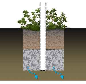
This type of bioretention facility provides the highest level of stormwater volume control. Although this design does not include an underdrain, an overflow pipe, a weir or other outlet structure must be included.
Planning considerations[edit]
Inlets[edit]
All forms of bioretention benefit hugely from the inclusion of pretreatment in the overall treatment train. The best type of pretreatment will depend on how the water enters into the facility. Mostly commonly this would be:
- sheet flow
- concentrated overland flow, or
- concentrated piped flow.
Distributed sheet flow is preferable to reduce the erosive energy of the water, and to promote infiltration across the surface of the practice.
Overflow and active storage[edit]
A plan should be in place for the conveyance of excess flow in the event that the facility is inundated during an extreme event. This may be to permit controlled overland flow to another facility, or to direct the flow to a pipe. In this case the invert of this pipe must be below the surrounding landscape to prevent accidental spilling. The depth between the top of the filter media/mulch and the invert of the overflow pipe is active storage of limited duration ponding and is sometimes referred to as the bowl depth. To prevent mosquito activity (and fear of mosquito activity), surface ponding time should be limited to 24 hours and should be calculated as 1D infiltration.
Design[edit]
Calculating Size[edit]
Bioretention facilities can be sized as other forms of subterranean infiltration facility. Infiltration: Sizing and modeling
Modeling
| Surface | |
|---|---|
| Berm height (mm) | Ponding depth, maximum (e.g. 300 mm), sometimes referred to as 'bowl depth' |
| Surface roughness (Manning’s n) | Lower numbers indicate less surface obstruction and result in faster flow
Suggested ranges:
|
| Surface slope (%) | If the slope > 3% a series of Check dams or weirs should be included in the design. |
| Soil (bioretention filter media) | |
| Thickness (mm) | Depth of filter media |
| Porosity of filter media | Suggest 0.35 unless otherwise tested |
| Field capacity (fraction) | Suggested range 0.10 - 0.12 [1] |
| Wilting point (fraction) | Suggested value 0.03 [1] |
| Hydraulic conductivity (mm/hr) | Suggested range 25 – 250 mm/hr |
| Conductivity slope | Suggested value 45 [1] |
| Suction head (mm) | Suggested range 50 - 60 [1] |
| Storage | |
| Thickness (mm) | Depth of storage aggregates layer |
| Porosity of storage reservoir aggregate | Suggest value 0.4 unless otherwise tested |
| Seepage rate (mm/hr) | Infiltration rate of native soil |
| Clogging factor | Maybe up to 0.5 to account for some anticipated maturation. |
| Design drainage time (hrs) | Maximum permissible time to fully drain the storage reservoir. |
| Drain (underdrain) | |
| Flow coefficient | Suggested value 1 |
| Flow exponent | Suggested value 1 |
| Offset height | This is the height from the base of the cell to the height at which the drain discharges. In some designs this may be the height of the perforated pipe within the storage layer; in others this height is adjusted by creating an upturn in the discharge pipe.Bioretention: Partial infiltration |
Materials[edit]
Performance[edit]
- ↑ 1.0 1.1 1.2 1.3 1.4 Oregon State Univ., Corvallis. Dept. of Civil, Construction and Environmental Engineering.; Environmental Protection Agency, Cincinnati ONRMRL. Storm Water Management Model Reference Manual Volume I Hydrology (Revised). 2016:233. https://nepis.epa.gov/Exe/ZyPURL.cgi?Dockey=P100NYRA.txt Accessed August 23, 2017.

