Filtration Manufactured Treatment Devices

Overview[edit]
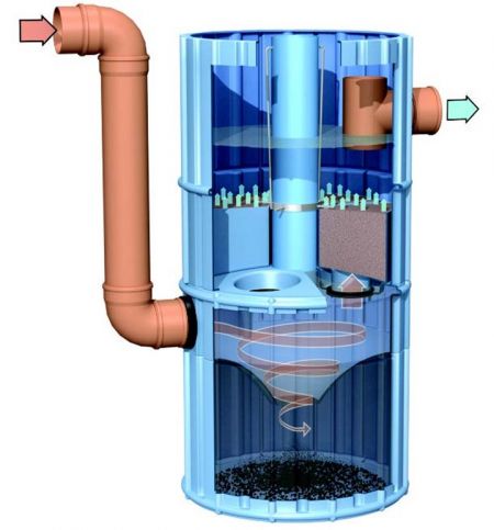
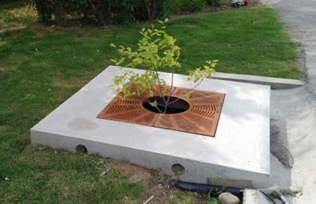
Filtration Manufactured Treatment Devices (MTDs) are structures with one or more chambers containing filtration media, membranes and/or filtration cartridges that remove solids and debris/trash from runoff. Some units may have oil separation functions and pretreatment chambers for coarse sediment and debris. The filter components are designed to remove the coarse and fine sediment fraction of suspended solids and associated pollutants in stormwater runoff and may also target removal of dissolved pollutants such as phosphorus or metals through biological and/or chemical processes.

Application[edit]
Filtration MTDs are suitable for pre-treatment or may be installed as stand alone if third party performance testing shows that they achieve enhanced level water quality protection (i.e. lower 95th percentile removal efficiencies of 80% or greater).
Since Filtration MTDs contain filters that restrict flow rates, they are normally designed for much lower hydraulic loading rates than Oil-Grit Separator MTDs and have longer detention times. Flow restriction occurs due to the small pore size openings of filters and the clogging of pores and/or the formation of films either on the surface of the filter or within the filter matrix filter. For this reason, inspection and maintenance intervals for Filtration MTDs are normally shorter than for OGS MTDs. The method of maintenance typically involves sediment removal with a hydro vacuum truck as well as filter cleaning or replacement.
Further guidance on how the data and information generated from verified laboratory testing of OGS technologies should be interpreted and factored into regulatory agency approvals and procurement decisions for stormwater management is provided in this publicly available specification Guidance on the Use and Application of Results from Verified Laboratory and Field Testing for Stormwater Manufactured Treatment Devices, developed by TRCA and the Standards Council of Canada that addresses both OGS and Filtration MTDs.
Testing and Verification[edit]
Testing of Filtration MTD performance must be based primarily on field monitoring. Field testing is particularly important for Filtration MTDs because stormwater sediments consist of a mixture of cohesive silts, clay, sand, and may include organic matter, emulsified oils, fine debris, bacteria and other pollutants that build up on filter surfaces and/or penetrate into the filter structure(s) resulting in clogging dynamics that may vary significantly across different filtration system designs. These clogging processes are not easily replicated in laboratory testing due to limitations on the type of test sediment that is used (non-cohesive ground silica) and other factors.
Field testing also allows for a more accurate assessment of filter performance for stormwater pollutants other than suspended solids. These pollutants are subject to complex physical, chemical, and biological interactions that are not easy to replicate in a laboratory.
In Canada, the Canadian Procedure for Field Testing of Filtration Manufactured Treatment Devices, developed by TRCA and the Standards Council of Canada stipulates field testing requirements for Filtration MTDs. This document was developed based on the Washington Technology Assessment Protocol – Ecology (TAPE). TAPE provides a robust and scientifically defensible field evaluation methodology for proprietary and non-proprietary stormwater treatment technologies that is well regarded by stormwater practitioners, having been developed and continuously updated over the past two decades through an extensive third-party expert peer review process.
It should be noted that several jurisdictions in Canada do not accept filtration MTDs without field monitoring due to the aforementioned concerns, even if a lab test has been verified through the ISO 14034 ETV process.
Performance Results[edit]
Existing ‘General Use Level Designation’ certification of Filtration MTDs through the Washington TAPE process may satisfy ETV testing requirements in Canada provided that the design of the tested unit has not changed, TAPE requirements were followed, and hydraulic laboratory testing is used only to augment, rather than replace field testing requirements. In some cases, additional testing and data analysis may be required to support the ISO 14034 verification.
A list of TAPE approved Filtration MTDs with General Use Designation can be found on the Washington TAPE website, along with technical reports for each device. You can find several Filtration MTDs on the TAPE approved list of stormwater technologies here: Emerging stormwater treatment technologies (TAPE), or click the button below:
The following table on the TAPE website lists the devices that have received a use designation through the TAPE process. These use designations can be divided into three separate Use Level Designation (ULD) categories:
- General Use Level Designation (GULD): Known technologies whose given evaluation report showcases that they can confidently achieve Washington state Technology Assessment Protocol - Ecology's required performance goals.
- Conditional Use Level Designation (CULD): These are technologies that should most likely and feasibly be able to meet stated performance goals, but the developer most conduct additional verification field testing (within a given time period) to achieve General Use Level designation.
- Pilot Use Level Designation (PULD): Newly piloted and promising emerging technologies whose use is specific to a given project's field testing requirements. Requires further verification testing though.
Scaling[edit]
Appropriate scaling ensures that performance results from the model tested and verified through TAPE and/or ISO 14034 ETV can be confidently applied to other model sizes for the same MTD. Buyers should ensure to ask vendors to provide sizing data and calculations to confirm that the proposed unit is scaled appropriately. Verifications conducted in 2023 or later will include information on unit scaling in the publicly available verification statement.
The scaling rules, as stated in the Canadian Procedure for Field Testing of Filtration MTDs[3], are as follows:
"Scaling the tested filtration MTD to determine other model sizes and performance without completing additional testing is acceptable provided that:
- The depth, composition, bulk density and gradation of media remain constant. Nominal pore size of membrane based filters remain constant;
- The ratio of the system treatment flow rate to effective filtration treatment area (filter surface area) is the same or less than the tested filtration MTD;
- The ratio of effective sedimentation treatment area to effective filtration treatment area is the same or greater than the tested filtration MTD; and
- The ratio of wet volume to effective filtration treatment area is the same or greater than the tested filtration MTD
Sizing[edit]
Appropriate sizing of Filtration MTDs is more complex than for Oil-Grit Separators because of the wide variation in different filtration device designs. Assessing whether performance of Filtration MTDs meets performance objectives for the site based on verified testing reports will require the following information:
- Historical rainfall records (≤ 1 hour recording intervals, 15 minute preferred where available) from the nearest long term meteorologic station for months when temperatures are predominantly above 0°C. Data should be filtered to account for the initial abstraction factor, which represents an assumed loss occurring during the initial phases of a storm and ends when the total rainfall depth equals the abstraction factor (e.g. 2 mm);
- Site drainage area size, impervious cover percentage and site runoff coefficient calculated based on pervious and impervious cover runoff coefficients relevant to the site drainage area (e.g. slope, soil texture) and jurisdiction;
- Treatment objective (normally denominated as a removal efficiency for water quality parameters of concern, but some jurisdictions may use effluent concentrations either in addition or instead of removal efficiencies) and location in drainage system (i.e. stand alone or as pretreatment to other downstream BMPs); indicate whether upstream flow control is provided, and if so, the type (e.g. parking lot storage, roof storage, pipe storage);
- Proposed model sizes and specifications (diameter or dimensions, internal sedimentation area, manufacturers recommended maintenance sediment storage depth, chamber depth, filter type and number, media composition – if relevant);
- Verification test results (from field monitoring through TAPE or equivalent): lower 95th percent confidence interval of mean pollutant removal efficiency for each water quality parameter; upper 95th percent confidence interval of mean effluent concentration for each parameter; lowest measured bypass flow rate, head loss data, and other relevant operational parameters;
- Design TSS runoff concentration for the site or jurisdiction
As with OGS, the Rational Method can be employed to estimate flow rates discharged to the MTD for the site in question based on historical rainfall records and the selected recording interval (≤1 hour, 15 minute preferred where available). These flow rates are in turn used to calculate hydraulic and sediment mass loading to the selected Filtration MTD model (TRCA, 2023)[4]. In general, sizing should ensure that at least 90% of the annual runoff volume during an average year is treated (i.e. does not exceed the system treatment flow rate as defined in Table 2 below).

| Design Parameter | Description |
|---|---|
| System treatment flow rate | The treatment flow rate represents the maximum flow rate that was conveyed through the treatment chamber during field testing without bypassing. The system bypass rate is greater than the system treatment flow rate. When the system treatment flow rate is expressed per unit sedimentation area, it is referred to as the system treatment surface loading rate. |
| Maximum filtration flux rate or media infiltration rate | The maximum filtration flux rate is a measure of the maximum treatment flow rate per unit filter surface area. For devices with membrane or media cartridges the rate is provided both per cartridge and for the total filtration surface area (multiple cartridges). For devices with media filters where flows are conveyed vertically from top to bottom the rate is expressed as an infiltration rate for the system. In both instances, the maximum filtration flux rate is determined from field testing as the lowest measured treatment flow rate prior to the onset of bypass, which would typically occur just before required filter maintenance. |
| Detention time | The detention time is the time required for water to be conveyed through the MTD at a given flow rate. It is influenced by the wet volume, or maximum volume in the MTD at a specified flow rate. |
| Design total suspended solids (TSS) runoff concentration | The suspended solids concentration in site runoff that is used to calculate sediment mass loading to the unit over the course of an average precipitation year. |
| Maintenance sediment storage depth and volume | The maintenance sediment storage depth/volume represents the storage depth/volume available for sedimentation either on top of the media filter or within the chamber housing the filter cartridges and pretreatment chamber(s) (if applicable), as recommended by the manufacturer and confirmed through field testing. The sump depth is constant across different unit sizes, but the sump volume increases in relation to the effective filtration area, as per the scaling rule noted above. |
The recommended maintenance frequency must adhere to the findings in the field test report or be shown through detailed design calculations to meet the approval agency maintenance interval requirements, with a buffer of safety added for uncertainties in site specific sediment, gross solids and debris loads. MTD inspections may need to be more frequent at sites where the site runoff quality is likely to lead to faster clogging of system filtration components than was observed in the field test. Some runoff quality parameters that may enhance clogging potential relative to the field test results may include the presence of a larger mass of finer particles (silts and clays), higher organic matter content or hydrocarbon loading, and higher bacterial loads, which can enhance the development of biofilms.
TAPE and/or ISO 14034 verified MTD vendor websites[edit]
There are numerous Filtration MTDs on the TAPE approved list of stormwater technologies, please find several below:
- StormGarden® Biofilter - Developed by: Rotondo Environmental Solutions
- BioPod™ - Developed by: Oldcastle Infrastructure, Inc.
- Aquip - Developed by: StormwateRx, LLC.
- Filterra System - Developed by: Contech Engineered Solutions, LLC.
- Jellyfish® Filter - Developed by: Contech Engineered Solutions, LLC.
- Kraken® Filter - Developed by: Contech Engineered Solutions, LLC.
- EcoPure BioFilter™ 3-Cell - Developed by: Advanced Drainage Systems
- Stormceptor - Developed by: Imbrium Systems
- HydroFilter - Developed by: HydroWorks
- Up-Flo Filter - Developed by: Hydro International Ltd.
- Hydro StormScape - Developed by: Hydro International Ltd.
- EnviroBasin™ - Developed by: EnviroPod Inc.
Disclaimer[edit]
In our effort to make this guide as functional as possible, we have decided to include proprietary systems and links to manufacturers websites. Inclusion of such links does not constitute endorsement by the Sustainable Technologies Evaluation Program. Lists are ordered alphabetically; link updates are welcomed using the form below.
References[edit]
- ↑ 3P Technik UK Ltd. 2023. HYDROSYSTEM1000 SUDS MULTI-PROCESS TREATMENT DEVICE. Multi-process SUDS Treatment Device Stages. Accessed: https://www.3ptechnik.co.uk/stormwater-treatment/hydrosystem_1000/
- ↑ STEP. 2020. Performance Evaluation of a High Rate Treatment Bioretention Filter Multi-process SUDS Treatment Device Stages. Technical Brief. Accessed: https://sustainabletechnologies.ca/app/uploads/2020/06/High-rate-treatment-bioretention-filter-tech-brief.pdf
- ↑ Toronto and Region Conservation Authority, 2023. Canadian Procedure for Field Testing of Stormwater Filtration Manufactured Treatment Devices: A Publicly Available Specification, Toronto, Ontario. https://sustainabletechnologies.ca/app/uploads/2023/11/SETV-Filtration-MTDs-PAS-2023-11-07-English.pdf
- ↑ TRCA. 2023. Guidance on the Use and Application of Results from Verified Laboratory and Field Testing for Stormwater Manufactured Treatment Devices. A Publicly Available Specification Prepared by: Toronto and Region Conservation Authority and Supported by: The Standards Council of Canada. June, 2023. Accessed: https://sustainabletechnologies.ca/app/uploads/2023/07/SETV-Guidance-PAS-2023-07-27-English.pdf
