Difference between revisions of "Inlets"
Jenny Hill (talk | contribs) m |
|||
| (17 intermediate revisions by 4 users not shown) | |||
| Line 1: | Line 1: | ||
| + | {{TOClimit|2}} | ||
| + | ==Overview== | ||
| + | Concentrated flow inlets are associated with LID practices such as [[Bioretention]], [[Stormwater planters]], [[Infiltration trenches]] and [[infiltration chambers|chambers]]. | ||
| + | Sheet flow alternatives include [[level spreaders]], [[gravel diaphragms]] and [[vegetated filter strips]]. | ||
| + | Practices such as [[permeable pavements]] and [[green roofs]] receive precipitation directly, whilst [[exfiltration trenches]] are connected directly to conventional storm sewers. | ||
| + | |||
Inlets for BMPs in the right of way should be located: | Inlets for BMPs in the right of way should be located: | ||
*At all sag points in the gutter grade | *At all sag points in the gutter grade | ||
*Immediately upgrade of median breaks, crosswalks, and street intersections. | *Immediately upgrade of median breaks, crosswalks, and street intersections. | ||
| − | It is | + | It is recommended to include multiple inlets, sized to distribute inflow along the length of the practice or between multiple facilities, where feasible, rather than concentrating all inflow into a single location. ([[Overflow|Offline overflow]]). |
| + | |||
| + | ==Trench drains== | ||
| + | Trench drains are long, covered channels that collect and direct water into the BMP. They are an excellent solution for streets where walking across the entire surface is to be encouraged. They can be designed as detectable edges or part of a detectable edge, and may be used to help define curbless or 'complete streets'. | ||
| + | |||
| + | Trenches may either be shallow (where runoff volume is less of an issue) or deep and covered by a metal grate. Deeper trench drains may gather sediment and require frequent maintenance. | ||
| + | |||
| + | Drains may be configured either perpendicular or parallel to the flow direction of the roadway, collecting runoff and directing to a single inlet in the BMP. | ||
| + | {{:Trench drains: Gallery}} | ||
| + | ==Curb cuts== | ||
| + | [[Curb cuts]] are breaks along the length of a curb system to allow water to flow into a LID/BMP. | ||
| + | |||
| + | Inlet aprons or depressions increase inflow effectiveness of curb cuts. Steeply angled aprons can be hazardous, especially to people bicycling. Curbside and protected bike lanes along concrete aprons should be at least 1.8 m to give cyclists adequate clear width from the curb and any pavement seams. Aprons can also be marked visually to indicate their perimeter. | ||
| + | For aprons into [[bioretention]], the curb may angle into the cell to improve conveyance of gutter flow into the facility. Aprons typically drop 50 mm into the bioretention cell, with another 50 mm drop behind the curb to maintain inflow as debris collects. | ||
| + | A depressed concrete apron can be cast in place or retrofitted in by grinding down the existing concrete pavement. | ||
| + | |||
| + | Where the curb alignment along the street is straight, the curb opening may optionally have a bar across the top of the inlet. | ||
| + | <gallery mode="packed" widths=200px heights=200px> | ||
| + | County Court Blvd biofilter spillway inlet and CB overflow.jpg|OPSD 605.040 Asphalt Spillway inlet to biofilter swale and road catch basin overflow outlet. County Court Blvd., Brampton, ON. | ||
| + | Curb inlet Miss Rd.jpg|This curb cut has been sawn into existing concrete as part of a retrofit. Note the temporary (erosion log) and permanent [[stone]] erosion control measures in place. Mississauga Road, ON. | ||
| + | LSRCA curb.jpg| [[Curb cuts|Curb cut]] used as a controlled [[overflow]] route from [[permeable pavements|permeable pavement]] to a [[bioretention]] facility with monitoring well, Lake Simcoe Region Conservation Authority, Newmarket, ON. | ||
| + | Curb cut CNT.jpg| Curb cut into a bioretention facility in Hinsdale, IL. [[Stone]] in the center of the facility reduces erosion and dissipates power inflow around the [[Inlets|inlet]] area. A monitoring/maintenance [[well]] can be seen in the foreground. Photo credit: [[Acknowledgements|CNT]] | ||
| + | Curb cut AV.jpg | Curb cut into a bioretention facility in Brown Deer, WI. Stone is used to reduce erosion around the inlet area. Photo credit: [[Acknowledgements|Aaron Volkening]] | ||
| + | Ajax_curb_inlet.JPG| Curb cut into a bioretention facility in Ajax, ON. | ||
| + | IMAX Stone Inlet.jpeg| [[Stone]] lined inlet at IMAX site in Mississauga | ||
| + | Curb inlet grade.jpg| The [[grading]] around this inlet prevents flow in the correct direction. i.e. from the pavement onto the grass. Not too critical in this example, as the surface is [[permeable pavements|permeable pavement]]. | ||
| + | </gallery> | ||
| + | |||
| + | ==Inlet sumps== | ||
| + | An inlet sump is recommended to settle and separate sediments from runoff where a large amount of debris is expected. Water drains into a catch basin, where debris settles in its sump. After [[pretreatment]], water drains via a pipe or opening into the BMP. The sump can be directly connected to a perforated [[underdrain]] pipe to distribute the flow to the [[bioretention]], supported [[soil cells]] or underground practices such as [[trenches]] or [[chambers]]. | ||
| + | |||
| + | Sump inlets should not be sited where pedestrians will have to negotiate with them. | ||
| + | {{:Inlet sumps: Gallery}} | ||
| + | ==Depressed drains== | ||
| + | Runoff in the gutter drops into a grate-covered drain before flowing into the BMP. Drain covers must be compatible with bicycling and walking; grid covers are preferred. | ||
| + | Depressed drains are a potential solution for bioretention cells on sloped streets where directing runoff into the cell is a challenge. | ||
| − | + | This style of inlet can be combined with a curb cut, to maintain capacity in case debris clogs the grate. | |
| − | + | {{Trench drains: Gallery}} | |
| − | |||
| − | |||
| − | |||
| − | |||
| − | |||
| − | |||
| − | |||
| − | |||
| − | |||
| − | |||
| − | |||
| − | |||
| − | |||
| − | |||
| − | |||
| − | |||
| − | |||
| − | |||
| − | |||
| − | |||
| − | |||
| − | |||
| − | |||
| − | |||
| − | |||
| − | |||
| − | |||
| − | |||
| − | |||
| − | |||
| − | |||
==External links== | ==External links== | ||
https://nacto.org/publication/urban-street-stormwater-guide/stormwater-elements/bioretention-design-considerations/inlet-design/ | https://nacto.org/publication/urban-street-stormwater-guide/stormwater-elements/bioretention-design-considerations/inlet-design/ | ||
Revision as of 20:59, 27 September 2022
Overview[edit]
Concentrated flow inlets are associated with LID practices such as Bioretention, Stormwater planters, Infiltration trenches and chambers. Sheet flow alternatives include level spreaders, gravel diaphragms and vegetated filter strips. Practices such as permeable pavements and green roofs receive precipitation directly, whilst exfiltration trenches are connected directly to conventional storm sewers.
Inlets for BMPs in the right of way should be located:
- At all sag points in the gutter grade
- Immediately upgrade of median breaks, crosswalks, and street intersections.
It is recommended to include multiple inlets, sized to distribute inflow along the length of the practice or between multiple facilities, where feasible, rather than concentrating all inflow into a single location. (Offline overflow).
Trench drains[edit]
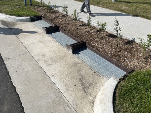
Trench drains are long, covered channels that collect and direct water into the BMP. They are an excellent solution for streets where walking across the entire surface is to be encouraged. They can be designed as detectable edges or part of a detectable edge, and may be used to help define curbless or 'complete streets'.
Trenches may either be shallow (where runoff volume is less of an issue) or deep and covered by a metal grate. Deeper trench drains may gather sediment and require frequent maintenance.
Drains may be configured either perpendicular or parallel to the flow direction of the roadway, collecting runoff and directing to a single inlet in the BMP.
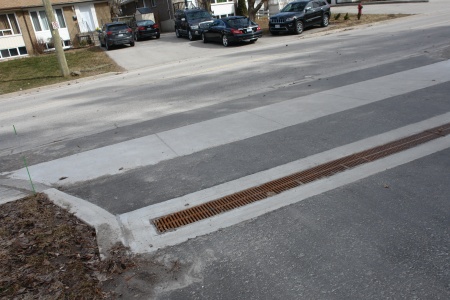
Combination of trench drain and winter shut off gate: King Street, Kitchener, ON
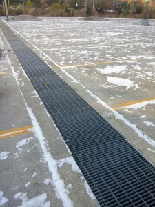
Trench drain that outlets to a bioswale at the LSRCA Office in Newmarket, ON
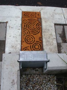
Bioretention system, or rain garden with a decorative trench drain cover, in Portland, US Taken in April 2013. Photo credit:EmilyBlueGreen
Curb cuts[edit]
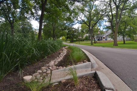
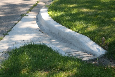
Curb cuts are breaks along the length of a curb system to allow water to flow into a LID/BMP.
Inlet aprons or depressions increase inflow effectiveness of curb cuts. Steeply angled aprons can be hazardous, especially to people bicycling. Curbside and protected bike lanes along concrete aprons should be at least 1.8 m to give cyclists adequate clear width from the curb and any pavement seams. Aprons can also be marked visually to indicate their perimeter. For aprons into bioretention, the curb may angle into the cell to improve conveyance of gutter flow into the facility. Aprons typically drop 50 mm into the bioretention cell, with another 50 mm drop behind the curb to maintain inflow as debris collects. A depressed concrete apron can be cast in place or retrofitted in by grinding down the existing concrete pavement.
Where the curb alignment along the street is straight, the curb opening may optionally have a bar across the top of the inlet.
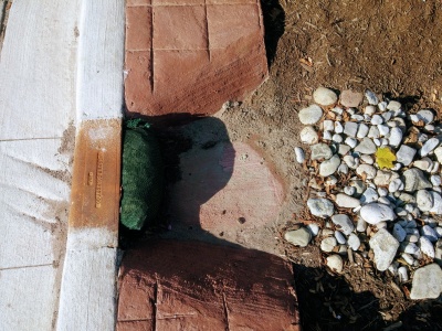
This curb cut has been sawn into existing concrete as part of a retrofit. Note the temporary (erosion log) and permanent stone erosion control measures in place. Mississauga Road, ON.
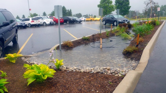
Curb cut used as a controlled overflow route from permeable pavement to a bioretention facility with monitoring well, Lake Simcoe Region Conservation Authority, Newmarket, ON.
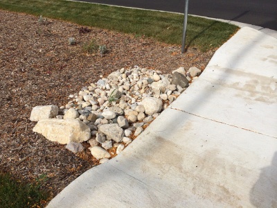
Curb cut into a bioretention facility in Brown Deer, WI. Stone is used to reduce erosion around the inlet area. Photo credit: Aaron Volkening
Stone lined inlet at IMAX site in Mississauga
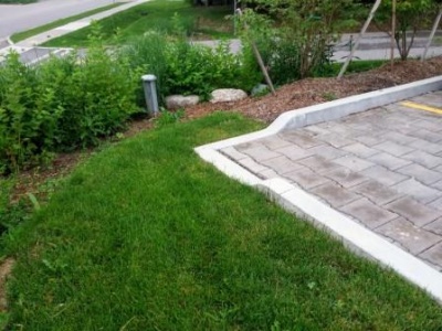
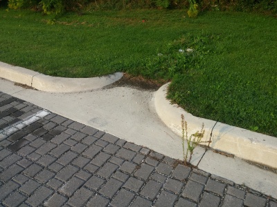
The grading around this inlet prevents flow in the correct direction. i.e. from the pavement onto the grass. Not too critical in this example, as the surface is permeable pavement.
Inlet sumps[edit]
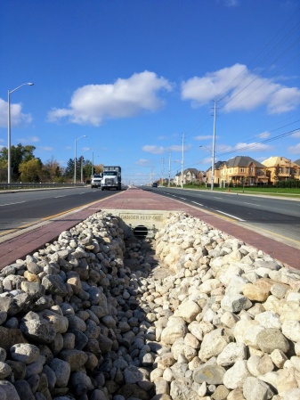
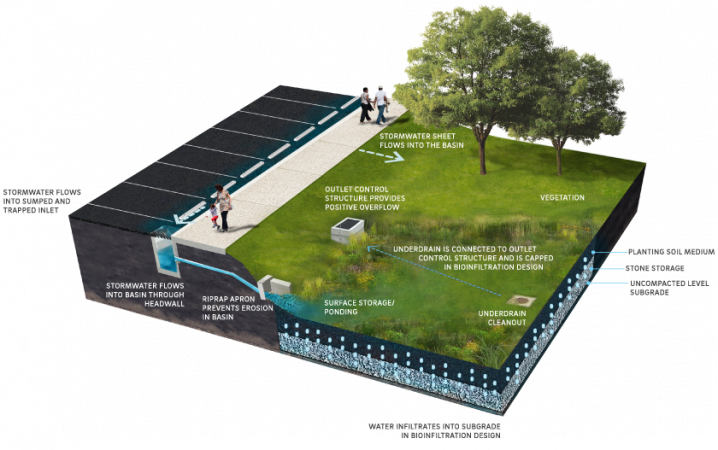
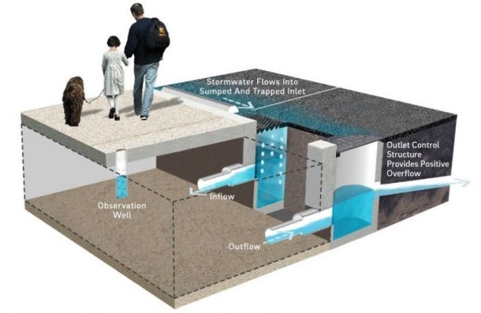
An inlet sump is recommended to settle and separate sediments from runoff where a large amount of debris is expected. Water drains into a catch basin, where debris settles in its sump. After pretreatment, water drains via a pipe or opening into the BMP. The sump can be directly connected to a perforated underdrain pipe to distribute the flow to the bioretention, supported soil cells or underground practices such as trenches or chambers.
Sump inlets should not be sited where pedestrians will have to negotiate with them.
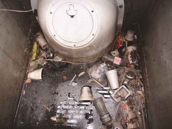
This pretreatment device, known as a baffle helps to remove trash, oil, TSS, larger sediments (silts, sands, etc.) and other floatables in roadway catch basins. This picture was taken of a SNOUT BAFL in Myrtle Beach, S.C. (Mullen, 2022)[1]
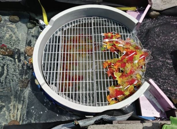
Example of an overland flow sump, capturing stormwater runoff from the adjacent roadway. This example showcases a Rain Guardian(TM) Turret structure with a metal grate overtop to capture larger floatables, trash and detritus from entering a stormwater facility or in this case a bioretention LID feature[2].
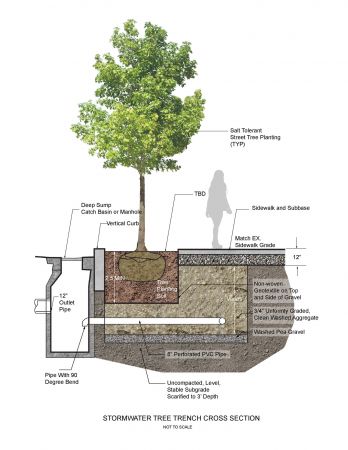
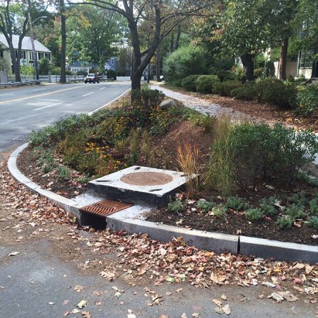
A stormwater tree trench, including a sump inlet design used as part of pretreatment. The feature is located in the City of Cambridge, Massachusetts, US. The design was developed and lead by HDR Inc., and Halvorson, Tighe & Bond Studio (Halvorson, Tighe & Bond Studio, n.d.)[3]
Example of a sump inlet being used in conjunction with a large bioretention basin feature, located in park space receiving stormwater off of the adjacent roadway (Source: Philadelphia Water Department, n.d.)[4]
An inlet sump leading into a bioretention bump out for traffic calming. Inlet sumps help both settle and separate sediment from stormwater road runoff before depositing excess sediment and silt into an infiltration BMP. These sumps allow stormwater to flow into the feature through an underdrain pipe (Source: NACTO, 2017)[5]
Example of a sump inlet allowing sediment to settle out of influent stormwater before entering a large infiltration chamber housed under the parking lot (Source: Philadelphia Water Department. 2020)[6]
Example of a proprietary inlet device known as a Rain Guardian Bunker, that was installed at the Morningside Extension Project in Scarborough, ON.
Depressed drains[edit]
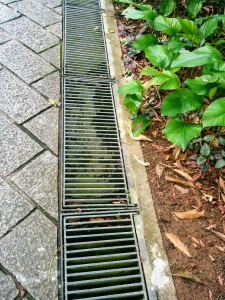
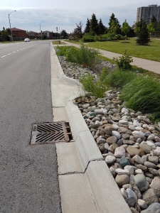
Runoff in the gutter drops into a grate-covered drain before flowing into the BMP. Drain covers must be compatible with bicycling and walking; grid covers are preferred. Depressed drains are a potential solution for bioretention cells on sloped streets where directing runoff into the cell is a challenge.
This style of inlet can be combined with a curb cut, to maintain capacity in case debris clogs the grate. Template:Trench drains: Gallery
External links[edit]
- ↑ Mullen, T.J. Prioritizing trash capture and clean oceans: Stormwater hoods and traps lead the way in effectiveness. The Municipal magazine. June 1, 2022. Accessed: https://www.themunicipal.com/2022/06/prioritizing-trash-capture-and-clean-oceans-stormwater-hoods-and-traps-lead-the-way-in-effectiveness/
- ↑ Erickson, A.J. and Hernick, M.A., 2019. Capture of Gross Solids and Sediment by Pretreatment Practices for Bioretention. Accessed: https://conservancy.umn.edu/handle/11299/201607
- ↑ Halvorson, Tighe & Bond Studio. n.d. Halvorson, Tighe & Bond Studio. Retrieved from: https://www.halvorsondesign.com/willard-street-drainage
- ↑ Philadelphia Water Department. n.d. Chapter 4 Stormwater Management Practice Guidance 4.1 Bioinfiltration/Bioretention. Retrieved from: https://water.phila.gov/development/stormwater-plan-review/manual/chapter-4/4-1-bioinfiltration-bioretention/
- ↑ National Association of City Transportation Officials (NACTO). 2017. Urban Street Stormwater Guide - Inlet Design. Retrieved from: https://nacto.org/publication/urban-street-stormwater-guide/stormwater-elements/bioretention-design-considerations/inlet-design/
- ↑ Philadelphia Water Department. 2020. Stormwater Management Guidance Manual: Version 3.2. Accessed from: https://www.pwdplanreview.org/upload/manual_pdfs/PWD-SMGM-v3.2-20201001.pdf
