Difference between revisions of "Enhanced grass swales"
Jenny Hill (talk | contribs) |
Jenny Hill (talk | contribs) |
||
| Line 15: | Line 15: | ||
==Planning considerations== | ==Planning considerations== | ||
<h3>Best X-section</h3> | <h3>Best X-section</h3> | ||
| − | [[File:Best X-section.png|thumb|Both sections a)triangular and, b)trapezoidal, are constrained within ratios of 8 | + | [[File:Best X-section.png|thumb|Both sections a)triangular and, b)trapezoidal, are constrained within ratios of 8:1 H:V]] |
| + | Enhanced swales aim to both reduce the flow rate and retain a portion of the conveyed water. For these purposes the best X-section is that which maximizes the wetted perimeter. The trapzoidal channel has the marginally greater hydraulic radius, but also the greater area. | ||
| + | {|class="wikitable" | ||
| + | |+ Examples worked without units, using the ratios given | ||
| + | |- | ||
| + | !Section | ||
| + | !Wetted perimeter | ||
| + | !Area | ||
| + | } | ||
Revision as of 15:05, 27 September 2017
This article is about installations designed to capture and convey surface runoff along a vegetated channel, whilst also promoting infiltration.
For underground conveyance which promotes infiltration, see Exfiltration trenches.
For conveyance along planted channels, on both surface and underground, see Bioswales.
Overview[edit]
The fundamental components of an enhanced grassed swale are:
- Graded channel
- Resilient turf grass
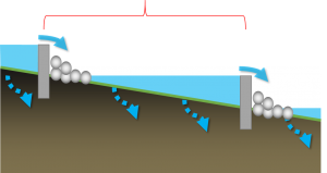
- Check dams, to facilitate short term ponding
Additional components may include:
- Amended soil, to increase infiltration to soils below
- Impermeable membrane, to prevent infiltration to soils below
- Turf reinforcement, to prevent scour
Planning considerations[edit]
Best X-section
Enhanced swales aim to both reduce the flow rate and retain a portion of the conveyed water. For these purposes the best X-section is that which maximizes the wetted perimeter. The trapzoidal channel has the marginally greater hydraulic radius, but also the greater area.
| Section | Wetted perimeter | Area
}
Check dams[edit]Check dams are small dams or weirs constructed across a drainage ditch, swale, or channel to lower the speed of concentrated flows for a certain design range of storm events and to promote infiltration. Check dams:
Sizing and spacing of check dams[edit]Check dams are a feature of enhanced grass swales. They promote infiltration and evaporation by promoting limited ponding. To design check dams into a swale:
The objective of these design recommendations are to maximize the distribution of ponded water along the whole BMP. Detailed design may require iteration of the dam heights and distances along each section of a long swale. To estimate the depth of water that can be infiltrated into a surface within a given time:
Where:
After surveying the longitudinal profile of the swale, the number of check dams for the swale can be calculated by using the following equation:
Where:
When spacing check dams, give preference to the narrowest parts of the swale in order to reduce construction costs. In this case, to establish the compensation gradient between the proposed check dams, proportionately increase the foundation depth of the upper check dam when the space between the lower and upper check dam is extended. When the space is shortened, decrease the foundation depth. As the foundation depth is increased, the total height of the check dam (effective height plus foundation depth) should not exceed the permissible, maximum total height. Example Calculation[edit]An enhanced swale of 42 m has an existing longitudinal slope of 6 %. The underlying soil has been amended to infiltrate at 16 mm/hr (after safety correction applied); the regulatory authority requires that ponded water must not remain for over 48 hours. The maximum height of the check dams (h) to prevent extended ponding is:: But the maximum recommended depth of check dams is 0.6 m (600 mm). (As an aside, these will drain in ) The current vertical distance along the swale is:: The desired effective slope to slow flow is 0.5%. The vertical distance along the swale with compensation gradient is:: The number of check dams required is:: This is rounded up to 4 dams, creating 5 ponding zones::
So the four check dams will be 0.6 m high and spaced every 8.4 m along the swale. These are fairly close together, but this construction is achievable and the dimensions are not remarkable, given the change in gradient is an order of magnitude. Design[edit]Swales should be designed to meet the following criteria:
Maximum depth of flow
Modeling
It is recommended that grass and enhanced grass swales be modelled using the 'Swale' element in the TTT. A 'swale' has to connect two existing elements within the TTT Bioswales or dry swales, which have amended filter media, should be modelled as bioretention cells. The alternative is to use the 'enhanced swale' within the LID toolbox, but this incorporates fewer design parameters (and doesn't account for infiltration).
Materials | ||||||||||||||||||||||||||||||||||||||||
|---|---|---|---|---|---|---|---|---|---|---|---|---|---|---|---|---|---|---|---|---|---|---|---|---|---|---|---|---|---|---|---|---|---|---|---|---|---|---|---|---|---|---|
- ↑ Jump up to: 1.0 1.1 Oregon State Univ., Corvallis. Dept. of Civil, Construction and Environmental Engineering.; Environmental Protection Agency, Cincinnati ONRMRL. Storm Water Management Model Reference Manual Volume I Hydrology (Revised). 2016:233.https://nepis.epa.gov/Exe/ZyPURL.cgi?Dockey=P100NYRA.txt Accessed August 23, 2017.


