Difference between revisions of "Drawings"
Jenny Hill (talk | contribs) m |
Dean Young (talk | contribs) |
||
| (86 intermediate revisions by 4 users not shown) | |||
| Line 1: | Line 1: | ||
{{float right|<pdf width="500" height="600">File:TO curb.pdf</pdf>}} | {{float right|<pdf width="500" height="600">File:TO curb.pdf</pdf>}} | ||
| − | + | ||
| − | If you want | + | |
| + | |||
| + | {{TOClimit|2}} | ||
| + | |||
| + | ==Overview== | ||
| + | This page provides a collection of links to design standard and drawing examples from Ontario and/or North American-based sources. | ||
| + | |||
| + | If you want help in finding example details for an LID design, please email the [mailto:lid.pd.guide@gmail.com Wiki Guide email account] or use the comment box below. | ||
{{textbox| 1= | {{textbox| 1= | ||
| − | You know that typical drawings are no substitute for | + | You know that typical drawings are no substitute for properly configured design!}} |
| + | |||
| + | ==Ontario Municipal Standards== | ||
| + | *[https://www.toronto.ca/services-payments/streets-parking-transportation/enhancing-our-streets-and-public-realm/green-streets/ City of Toronto] Green Streets program has produced "typical" road cross-section drawings for a wide variety of road types and contexts. See example of [[curb extensions]] to the right.<ref>https://www.toronto.ca/services-payments/streets-parking-transportation/enhancing-our-streets-and-public-realm/green-streets/</ref> | ||
| + | *[https://www.toronto.ca/services-payments/building-construction/infrastructure-city-construction/construction-standards-permits/standards-for-designing-and-constructing-city-infrastructure/construction-specifications-drawings-for-green-infrastructure/ City of Toronto, Construction Specifications and Drawings for Green Infrastructure] include many LID standard drawings, cross sections and details. See some examples below. <ref>https://www.toronto.ca/services-payments/building-construction/infrastructure-city-construction/construction-standards-permits/standards-for-designing-and-constructing-city-infrastructure/construction-specifications-drawings-for-green-infrastructure/</ref> | ||
| + | *City of Kitchener has standard details for [https://www.kitchener.ca/en/development-and-construction/development-manual.aspx pervious concrete pavement, precast permeable interlocking pavement and permeable pipe exfiltration systems], a note - you will have to send them an email requesting access to their development manual<ref>https://www.kitchener.ca/en/development-and-construction/development-manual.aspx</ref>. | ||
| + | *City of Cambridge's, Stormwater Management Policies and Guidelines [https://www.cambridge.ca/en/learn-about/resources/Stormwater-Management-Policy.pdf show typical cross section drawings for dry ponds, constructed wetlands, bioretention, etc.]. <ref>https://www.cambridge.ca/en/learn-about/resources/Stormwater-Management-Policy.pdf</ref> | ||
| + | |||
| + | ==Exfiltration Systems== | ||
| + | |||
| + | Please see below a Profile view of an exfiltration system (or perforated pipe system) designed for use in the City of Barrie and used in conjunction with a typical storm sewer system. '''Note''': This cross section installment is 'not located within a WHPA', although the source document for this drawing showcases a similar design configuration, that is 'located within a WHPA', which is not supported by STEP. | ||
| + | |||
| + | Drawings are from the City of Barrie's, [https://www.barrie.ca/government-news/adopted-strategies-plans/drainage-master-plan Drainage Master Plan] <ref>https://www.barrie.ca/government-news/adopted-strategies-plans/drainage-master-plan</ref> document. For further details about these cross section drawings please visit the link. | ||
| + | |||
| + | [[File:Exfiltration trench.PNG|1200px]] | ||
| + | |||
| + | ==Infiltration Trenches, Chambers & Soakaways== | ||
| + | |||
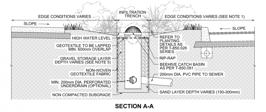
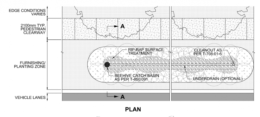
| + | Please see below a profile and plan view of an infiltration trench designed to treat and temporarily store stormwater for use in the City of Toronto located within the laneway between the road and sidewalk in a heavily urbanized location. This drawing depicts the use of an underdrain in the system where remaining stormwater runoff is directed to the nearby storm sewer system. | ||
| + | |||
| + | Drawings are from the City of Toronto's, [https://www.toronto.ca/services-payments/building-construction/infrastructure-city-construction/construction-standards-permits/standards-for-designing-and-constructing-city-infrastructure/construction-specifications-drawings-for-green-infrastructure/?accordion=green-infrastructure-drawings Design Criteria for Green Infrastructure in the Right-of-Way] <ref>https://www.toronto.ca/services-payments/building-construction/infrastructure-city-construction/construction-standards-permits/standards-for-designing-and-constructing-city-infrastructure/construction-specifications-drawings-for-green-infrastructure/?accordion=green-infrastructure-drawings Design Criteria for Green Infrastructure in the Right-of-Way </ref> document. For further details about these cross section drawings please visit the link. | ||
| + | |||
| + | [[File:Infiltration profile.PNG|900px|]] | ||
| + | |||
| + | |||
| + | [[File:Infiltration plan.PNG|900px|]] | ||
| + | |||
| + | |||
| + | |||
| + | |||
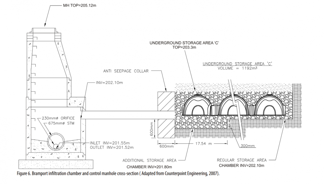
| + | Please see below a profile view of an infiltration chamber installed below a parking lot in a shopping centre development in Brampton, Ontario. The stormwater chamber system receives roof, road and parking lot runoff from a large drainage area that then drains to a receiving waterbody. The system was designed to provide temporary storage and controlled release of runoff from storms to minimize impacts to the receiving waterbody (elevated water temperatures, higher velocity flows, potential for elevated flood conditions, etc.). A 0.3m deep gravel bed with no outlet below a portion of the chamber area provides additional water storage in the event of a large or prolonged storm/rainfall event to provide better retention of sediment and the means to evaluate whether or not substantial infiltration occurs. Orifice flow restricting plates mounted on the outlets of each manhole cause stormwater to back up into the chambers and contributing storm sewers so that when flow into the manhole exceeds the maximum flow rate of the orifice plate, stormwater backs up into the chambers safely. | ||
| + | |||
| + | Drawings are from STEP's, [https://sustainabletechnologies.ca/app/uploads/2015/04/UndergroundInfiltrationSystems_TechBrief_April2015.pdf Technical Brief - Evaluation of Underground Stormwater Infiltration Systems document].<ref>https://sustainabletechnologies.ca/app/uploads/2015/04/UndergroundInfiltrationSystems_TechBrief_April2015.pdf </ref> The drawing was adapted from ''Counterpoint Engineering - Bramport Commercial Development, City of Brampton, Airport Road and Bovaird Drive – Site Servicing Plan Drawing No. SW-S1. Project No. 04160. May 7, 2007. Vaughan, ON''. For further details about this cross section drawing please visit the link. | ||
| + | |||
| + | [[File:Infiltration chamber profile.PNG|1100px]] | ||
| + | |||
| + | |||
| + | |||
| + | |||
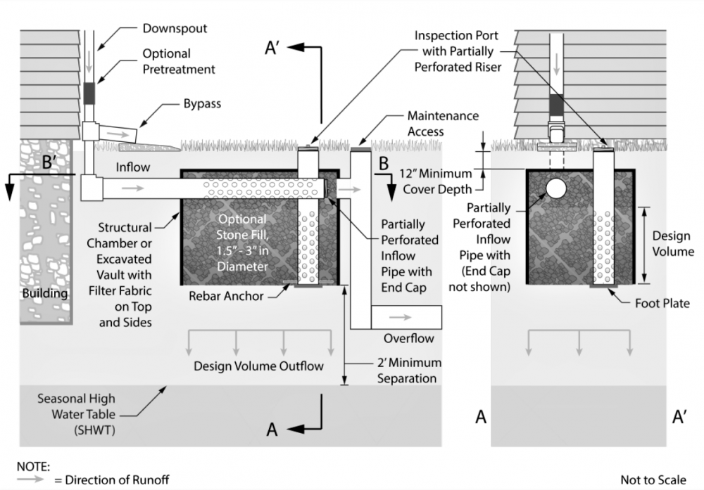
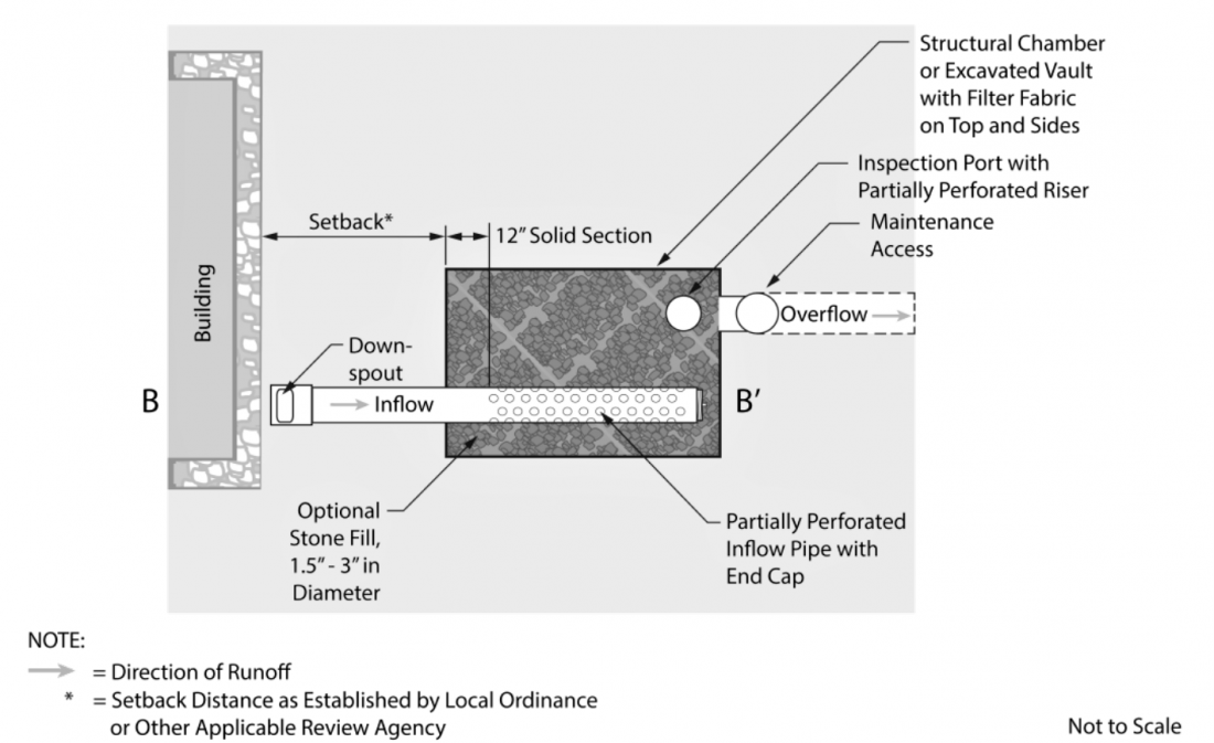
| + | Please see below a profile and plan view of a soakaway (also known as a dry well) installed on a residential property connected to the home's downspout. The drawing depicts how the installation can be installed with a typical downspout disconnection (or bypass), and fitted with an overflow that connects to the home's stormwater lateral that then enters the municipal system. This configuration of a soakway allows for full infiltration and includes an inspection port for monitoring purposes. | ||
| + | |||
| + | Drawings are from the New Jersey Department of Environmental Protection's [https://www.njstormwater.org/bmp_manual2.htm NJ Stormwater Best Management Practices Manual]. <ref>https://www.njstormwater.org/bmp_manual2.htm</ref>. For further details about this cross section drawing and other LID BMPs please visit the link. | ||
| + | |||
| + | [[File:Residential soakaway profile.PNG|1000px]] | ||
| − | == | + | [[File:Residential soakaway plan.PNG|1100px]] |
| − | + | ||
| + | ==Bioretention== | ||
| + | |||
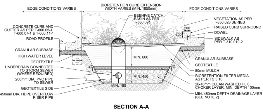
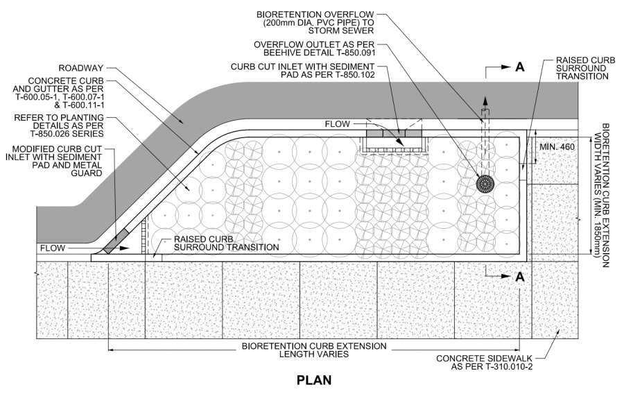
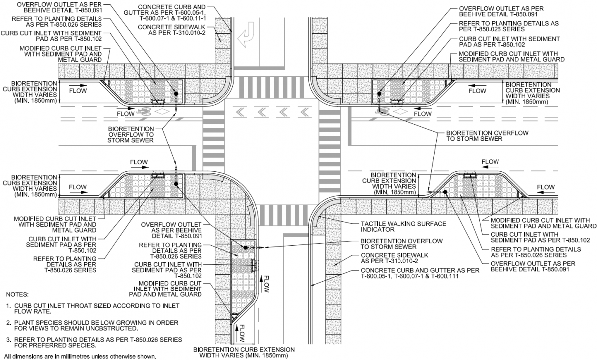
| + | Please see below a profile and plan view (along with a larger scale intersection plan view) of a bioretention facility designed in an urban [[curb extension|curb extension/"bump-out"]] designed to both calm traffic, enhance green space in an urban setting and treat overflow/runoff from the nearby street. Given that the bioretention installation is bound entirely with impermeable hardscape there is limited options for pretreatment. In the cross-sections shown below the pretreatments included in the installation are the inclusion of sediment traps [[Pretreatment features|sediment traps - a type of forebay]], which dissipate incoming flow into the feature and causes suspended sediment to settle out of the water. This allows for accumulated sediment to be cleaned out during general maintenance of the bioretention feature. | ||
| + | |||
| + | An excellent opportunity for integrating more bioretention into the street is through careful design of curb extensions for traffic control <ref>https://greenactioncentre.ca/healthy-travel/traffic-calming-101/#:~:text=A%20curb%20extension%2C%20or%20curb,to%20reduce%20speed%20(above)</ref>. See [[Roadside safety]] for design advice specific to this application. This drawing also depicts partial exfiltration with an installed underdrain as soils in this feature possess infiltration rates lower than 15mm/hr, and possesses several plantings. Remaining stormwater runoff is directed to the nearby storm sewer system. | ||
| + | |||
| + | Drawings are from the City of Toronto's, [https://www.toronto.ca/services-payments/building-construction/infrastructure-city-construction/construction-standards-permits/standards-for-designing-and-constructing-city-infrastructure/construction-specifications-drawings-for-green-infrastructure/?accordion=green-infrastructure-drawings Design Criteria for Green Infrastructure in the Right-of-Way] <ref>https://www.toronto.ca/services-payments/building-construction/infrastructure-city-construction/construction-standards-permits/standards-for-designing-and-constructing-city-infrastructure/construction-specifications-drawings-for-green-infrastructure/?accordion=green-infrastructure-drawings Design Criteria for Green Infrastructure in the Right-of-Way </ref> document. For further details about these cross section drawings please visit the link. | ||
| + | |||
| + | |||
| + | |||
| + | |||
| + | |||
| + | [[File:Bioretention profile.PNG|900px|]] | ||
| + | |||
| + | |||
| + | |||
| + | |||
| + | |||
| + | [[File:Bioretention plan.PNG|900px|]] | ||
| + | |||
| + | |||
| + | |||
| + | |||
| + | [[File:Bioretention highplanview.PNG|1200px|]] | ||
| + | |||
| + | ==Green Roof== | ||
| + | |||
| + | Please see below a profile view of a standard extensive green roof with a stone buffer layer, growing medium, filter layer, drainage layer, root barrier/protection layer, waterproof membrane and vapour barrier. What makes the following drawing an extensive green roof is that it consists of a thinner planting medium layer ( ≤15 cm deep) with herbaceous vegetative cover that possess shallower root systems and is designed for SWM purposes, and generally don't provide public access. | ||
| + | |||
| + | Drawing is from Metro Vancouver's, [http://www.metrovancouver.org/services/liquid-waste/LiquidWastePublications/StormwaterSourceControlDesignGuidelines2012StormwaterSourceControlDesignGuidelines2012.pdf Stormwater Source Control Design Guidelines document] <ref>http://www.metrovancouver.org/services/liquid-waste/LiquidWastePublications/StormwaterSourceControlDesignGuidelines2012StormwaterSourceControlDesignGuidelines2012.pdf Stormwater Source Control Design Guidelines </ref> document. For further details about these cross section drawings please visit the link. | ||
| + | |||
| + | |||
| + | [[File:Green roof extensive profile.PNG|900px]] | ||
| + | |||
| + | ==Permeable Pavements== | ||
| + | |||
| + | Please see below a profile and plan view of a drawing of a standard permeable pavement composed of interlocking pavers located in a parking lot/laneway (location dependent upon estimated traffic and vehicular loading). The installation is designed with an underdrain in this drawing as the site has low permeability soil (< 15mm/hr), allowing for only partial infiltration in the system. The permeable paver installation also includes a cleanout for said underdrain in case of clogging, and is comprised of a crushed aggregate bedding layer, clean washed stone base, and subbase (more about these layers can be found under here [[OPSS aggregates]] & [[Choker layer]]). The entire facility is surrounded by a geotextile to retain these layers and separate them from the underlying soil subgrade, allowing the system to infiltrate water into the surrounding soil and prevent migration amongst said layers. | ||
| + | |||
| + | Drawings are from the City of Toronto's, [https://www.toronto.ca/services-payments/building-construction/infrastructure-city-construction/construction-standards-permits/standards-for-designing-and-constructing-city-infrastructure/construction-specifications-drawings-for-green-infrastructure/?accordion=green-infrastructure-drawings Design Criteria for Green Infrastructure in the Right-of-Way] <ref>https://www.toronto.ca/services-payments/building-construction/infrastructure-city-construction/construction-standards-permits/standards-for-designing-and-constructing-city-infrastructure/construction-specifications-drawings-for-green-infrastructure/?accordion=green-infrastructure-drawings Design Criteria for Green Infrastructure in the Right-of-Way </ref> document. For further details about these cross section drawings please visit the link. | ||
| + | |||
| + | |||
| + | |||
| + | [[File:Permeable paver profile.PNG|1000px]] | ||
| + | |||
| + | |||
| + | |||
| + | |||
| + | [[File:Permeabel paver plan.PNG|1000px]] | ||
| + | |||
| + | ==Rainwater Harvesting== | ||
| + | |||
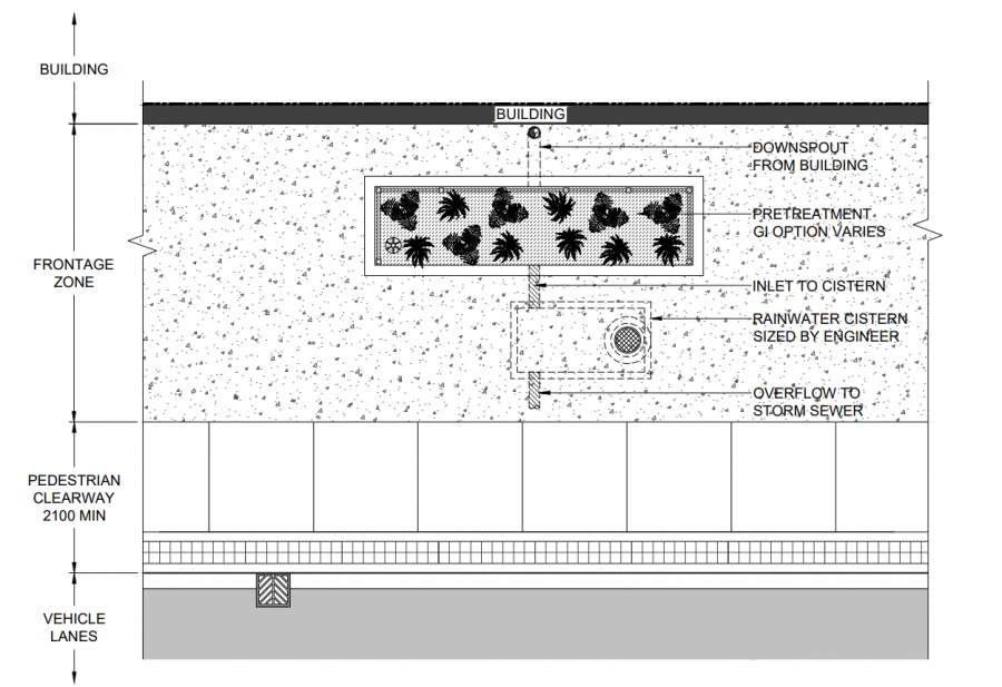
| + | Please see below a profile and plan view of a drawing of a standard rainwater harvesting cistern located on a private/public property's frontage with either a high water table or contaminated subsoils, connected to the building's downspout. This example includes the use of a raingarden as a pretreatment option, along with an underdrain and overflow which both deposit treated rainwater into the holding cistern. If water is not used for irrigation purposes, etc. there is an attached overflow which connects to the municipality's storm sewer system. | ||
| + | |||
| + | Drawings are from the [https://www.toronto.ca/ext/digital_comm/pdfs/transportation-services/green-streets-technical-guidelines-appendices-v2-17-11-08.pdf City of Toronto's Green Streets Technical Guidelines Appendices] <ref>https://www.toronto.ca/services-payments/building-construction/infrastructure-city-construction/construction-standards-permits/standards-for-designing-and-constructing-city-infrastructure/construction-specifications-drawings-for-green-infrastructure/?accordion=green-infrastructure-drawings Design Criteria for Green Infrastructure in the Right-of-Way </ref> document. For further details about these cross section drawings please visit the link. | ||
| + | |||
| + | |||
| + | [[File:Rainwater harvesting profile.PNG|1000px]] | ||
| + | [[File:Rainwater harvesting plan.PNG|900px]] | ||
| + | |||
| + | ==Bioswales / Enhanced Swales== | ||
| + | |||
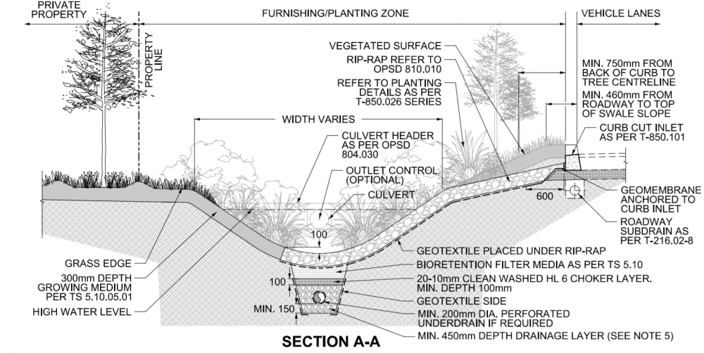
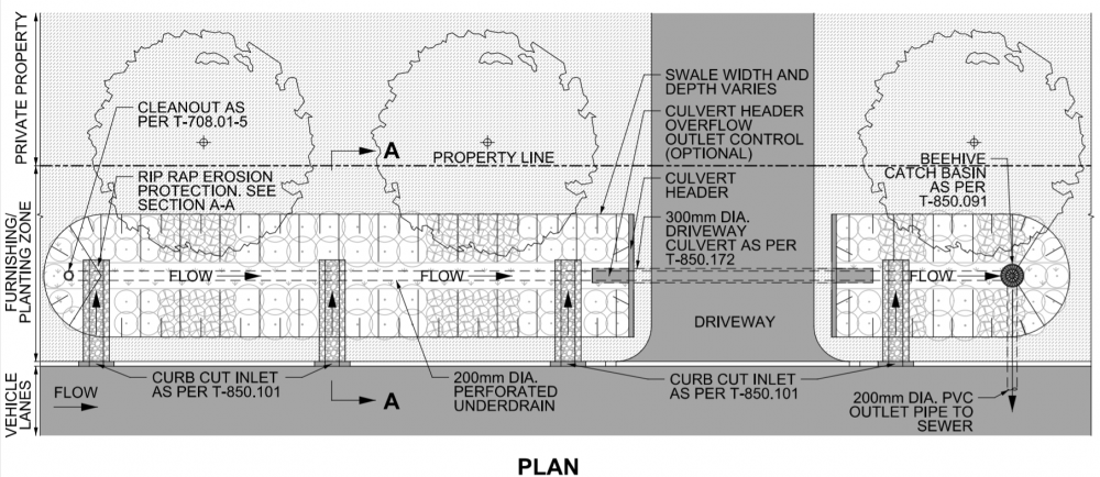
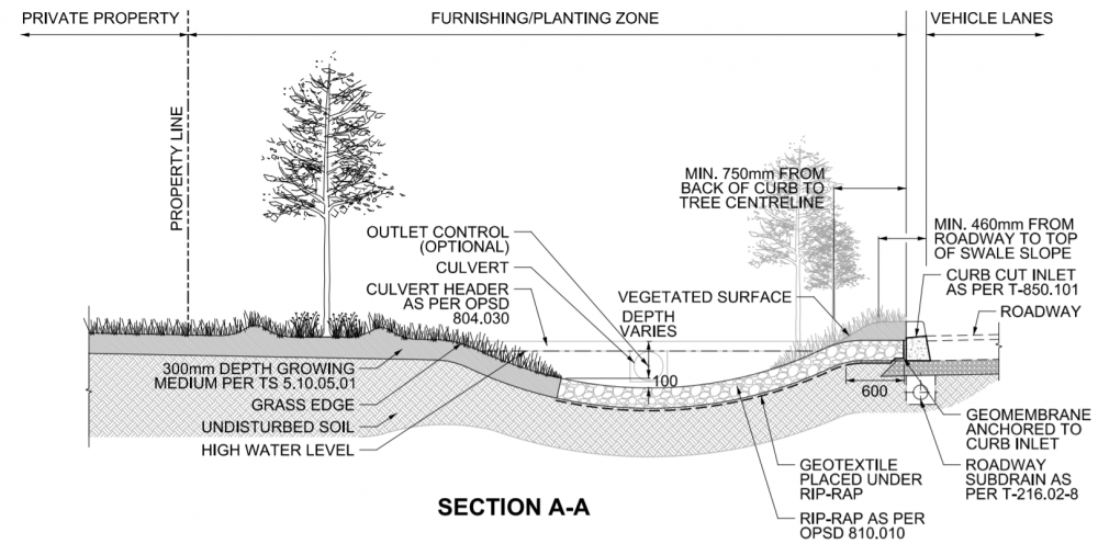
| + | Please find below two sets of profile and plan view drawings of a bioswale and enhanced swale installation. Both installations are located in between the front of a private homeowners' property and the roadway, known as a easement or frontage. The major difference between the two installations is the use of an underdrain for the bioswale, drainage layers, specialized filter media located underneath the geotextile underlain rip-rap so that it provides partial infiltration. Whereas, the enhanced swale provides full infiltration, through a fully vegetated surface, allowing water to travel down slowly to the undisturbed soil substrate below. | ||
| + | |||
| + | Drawings are from the City of Toronto's, [https://www.toronto.ca/services-payments/building-construction/infrastructure-city-construction/construction-standards-permits/standards-for-designing-and-constructing-city-infrastructure/construction-specifications-drawings-for-green-infrastructure/?accordion=green-infrastructure-drawings Design Criteria for Green Infrastructure in the Right-of-Way] <ref>https://www.toronto.ca/services-payments/building-construction/infrastructure-city-construction/construction-standards-permits/standards-for-designing-and-constructing-city-infrastructure/construction-specifications-drawings-for-green-infrastructure/?accordion=green-infrastructure-drawings Design Criteria for Green Infrastructure in the Right-of-Way </ref> document. For further details about these cross section drawings please visit the link. | ||
| + | |||
| + | |||
| + | [[File:Bioswale profile.PNG|1000px]] | ||
| + | |||
| + | |||
| + | |||
| + | [[File:Bioswale plan.PNG|1000px]] | ||
| + | |||
| + | |||
| + | |||
| + | |||
| + | |||
| + | |||
| + | |||
| + | |||
| + | [[File:EnhancedSwale profile.PNG|1000px]] | ||
| + | |||
| + | |||
| + | |||
| + | [[File:EnhancedSwale plan.PNG|1000px]] | ||
| + | |||
| + | ==Stormwater Tree Trenches== | ||
| + | Please see below a plan and profile view of one of several variations of a stormwater planter (soil cell) along a roadway. This type of cross section installment showcases a tree trench in a continuous growing medium located under a hard boulevard/concrete surface that can withstand constant and heavy vehicular loads. Drawings are from the [https://www.toronto.ca/ext/digital_comm/pdfs/transportation-services/green-streets-technical-guidelines-appendices-v2-17-11-08.pdf City of Toronto's Green Streets Technical Guidelines Appendices] document. For further details about these cross section drawings please visit the link. | ||
| + | |||
| + | [[File:Soil Cell Profile View.PNG|1000px]] | ||
| + | |||
| + | [[File:Soil Cell Plan View.PNG|900px]] | ||
| + | |||
| + | ==Rain Gardens== | ||
| + | Please see below a plan and profile view of a rain garden, which possesses full infiltration and bioretention functions. In the plan view, note that the contributing area has water coming from both the building's roof, and paved areas, along with the driveway and directed towards the lowest area of the property, where the rain garden is located. This allows the feature to collect and to easily absorb rain and surface water into the ground on homeowners/businesses' properties. The installation also includes a pretreatment rock/concrete forebay to limit erosion and reduce higher velocity flows entering the rain garden, along with mulch, filter media and various planting zones with specific vegetation types that are best suited for these areas within the feature to assist in infiltration and removal of contaminants. | ||
| + | |||
| + | Drawings are from the [https://www.cityofvancouver.us/publicworks/page/surface-waterstormwater-design-construction-requirements City of Vancouver's Surface Water/Stormwater Design & Construction Requirements] document.<ref>https://www.cityofvancouver.us/publicworks/page/surface-waterstormwater-design-construction-requirements</ref> For further details about these cross section drawings please visit the link. | ||
| + | |||
| + | |||
| + | [[File:Rain Garden profile.PNG|1000px]] | ||
| + | |||
| + | |||
| + | |||
| + | |||
| + | |||
| + | [[File:Rain Garden plan.PNG|900px]] | ||
| + | |||
| + | ==External Drawing Cross Sections== | ||
| + | *[http://webcast.ottawa.ca/plan/All_Image%20Referencing_OP%20Amendment%20Application_Image%20Reference_Rockcliffe%20-%20Low%20Impact%20Development%20Report%20-%20Part%204.PDF City of Ottawa - LID Demonstration Project] by Aquafor Beech Ltd. | ||
| + | *[http://extension.oregonstate.edu/stormwater/standard-details Oregon State University LID typicals] by GreenGirl | ||
| + | *[https://www.lid-stormwater.net/design_examples.htm Plan drawings] by Low Impact Development Center, Inc. | ||
| + | *[https://www.pwdplanreview.org/upload/pdf/PWD_Stormwater_Details_Bioinfiltration_Bioretention_Basin.dwg Bioretention detail] by Philly Water | ||
| + | *[https://www.pwdplanreview.org/upload/pdf/PWD_Stormwater_Details_Porous_Pavement.dwg Permeable paving] by Philly Water | ||
| + | *[https://www.pwdplanreview.org/upload/pdf/PWD_Stormwater_Details_Subsurface_Infil_Basin.dwg Pipe-in-stone infiltration] by Philly Water | ||
| − | |||
| − | |||
==Proprietary== | ==Proprietary== | ||
{{:Disclaimer}} | {{:Disclaimer}} | ||
*[http://www.ads-pipecanada.ca/en/documentlisting.asp?documenttypeID=5 ADS pipe] | *[http://www.ads-pipecanada.ca/en/documentlisting.asp?documenttypeID=5 ADS pipe] | ||
| + | *[http://www.deeproot.com/products/silva-cell/resources.html Soil cells] by Silvacell | ||
| + | *[https://www.hydro-int.com/en/resources/first-defense-dwg-drawings pretreatment] by Hydro International | ||
| + | |||
| + | ==References== | ||
Latest revision as of 17:40, 2 December 2022
Overview[edit]
This page provides a collection of links to design standard and drawing examples from Ontario and/or North American-based sources.
If you want help in finding example details for an LID design, please email the Wiki Guide email account or use the comment box below.
You know that typical drawings are no substitute for properly configured design!
Ontario Municipal Standards[edit]
- City of Toronto Green Streets program has produced "typical" road cross-section drawings for a wide variety of road types and contexts. See example of curb extensions to the right.[1]
- City of Toronto, Construction Specifications and Drawings for Green Infrastructure include many LID standard drawings, cross sections and details. See some examples below. [2]
- City of Kitchener has standard details for pervious concrete pavement, precast permeable interlocking pavement and permeable pipe exfiltration systems, a note - you will have to send them an email requesting access to their development manual[3].
- City of Cambridge's, Stormwater Management Policies and Guidelines show typical cross section drawings for dry ponds, constructed wetlands, bioretention, etc.. [4]
Exfiltration Systems[edit]
Please see below a Profile view of an exfiltration system (or perforated pipe system) designed for use in the City of Barrie and used in conjunction with a typical storm sewer system. Note: This cross section installment is 'not located within a WHPA', although the source document for this drawing showcases a similar design configuration, that is 'located within a WHPA', which is not supported by STEP.
Drawings are from the City of Barrie's, Drainage Master Plan [5] document. For further details about these cross section drawings please visit the link.
Infiltration Trenches, Chambers & Soakaways[edit]
Please see below a profile and plan view of an infiltration trench designed to treat and temporarily store stormwater for use in the City of Toronto located within the laneway between the road and sidewalk in a heavily urbanized location. This drawing depicts the use of an underdrain in the system where remaining stormwater runoff is directed to the nearby storm sewer system.
Drawings are from the City of Toronto's, Design Criteria for Green Infrastructure in the Right-of-Way [6] document. For further details about these cross section drawings please visit the link.
Please see below a profile view of an infiltration chamber installed below a parking lot in a shopping centre development in Brampton, Ontario. The stormwater chamber system receives roof, road and parking lot runoff from a large drainage area that then drains to a receiving waterbody. The system was designed to provide temporary storage and controlled release of runoff from storms to minimize impacts to the receiving waterbody (elevated water temperatures, higher velocity flows, potential for elevated flood conditions, etc.). A 0.3m deep gravel bed with no outlet below a portion of the chamber area provides additional water storage in the event of a large or prolonged storm/rainfall event to provide better retention of sediment and the means to evaluate whether or not substantial infiltration occurs. Orifice flow restricting plates mounted on the outlets of each manhole cause stormwater to back up into the chambers and contributing storm sewers so that when flow into the manhole exceeds the maximum flow rate of the orifice plate, stormwater backs up into the chambers safely.
Drawings are from STEP's, Technical Brief - Evaluation of Underground Stormwater Infiltration Systems document.[7] The drawing was adapted from Counterpoint Engineering - Bramport Commercial Development, City of Brampton, Airport Road and Bovaird Drive – Site Servicing Plan Drawing No. SW-S1. Project No. 04160. May 7, 2007. Vaughan, ON. For further details about this cross section drawing please visit the link.
Please see below a profile and plan view of a soakaway (also known as a dry well) installed on a residential property connected to the home's downspout. The drawing depicts how the installation can be installed with a typical downspout disconnection (or bypass), and fitted with an overflow that connects to the home's stormwater lateral that then enters the municipal system. This configuration of a soakway allows for full infiltration and includes an inspection port for monitoring purposes.
Drawings are from the New Jersey Department of Environmental Protection's NJ Stormwater Best Management Practices Manual. [8]. For further details about this cross section drawing and other LID BMPs please visit the link.
Bioretention[edit]
Please see below a profile and plan view (along with a larger scale intersection plan view) of a bioretention facility designed in an urban curb extension/"bump-out" designed to both calm traffic, enhance green space in an urban setting and treat overflow/runoff from the nearby street. Given that the bioretention installation is bound entirely with impermeable hardscape there is limited options for pretreatment. In the cross-sections shown below the pretreatments included in the installation are the inclusion of sediment traps sediment traps - a type of forebay, which dissipate incoming flow into the feature and causes suspended sediment to settle out of the water. This allows for accumulated sediment to be cleaned out during general maintenance of the bioretention feature.
An excellent opportunity for integrating more bioretention into the street is through careful design of curb extensions for traffic control [9]. See Roadside safety for design advice specific to this application. This drawing also depicts partial exfiltration with an installed underdrain as soils in this feature possess infiltration rates lower than 15mm/hr, and possesses several plantings. Remaining stormwater runoff is directed to the nearby storm sewer system.
Drawings are from the City of Toronto's, Design Criteria for Green Infrastructure in the Right-of-Way [10] document. For further details about these cross section drawings please visit the link.
Green Roof[edit]
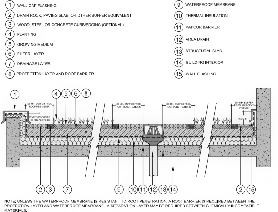
Please see below a profile view of a standard extensive green roof with a stone buffer layer, growing medium, filter layer, drainage layer, root barrier/protection layer, waterproof membrane and vapour barrier. What makes the following drawing an extensive green roof is that it consists of a thinner planting medium layer ( ≤15 cm deep) with herbaceous vegetative cover that possess shallower root systems and is designed for SWM purposes, and generally don't provide public access.
Drawing is from Metro Vancouver's, Stormwater Source Control Design Guidelines document [11] document. For further details about these cross section drawings please visit the link.
Permeable Pavements[edit]
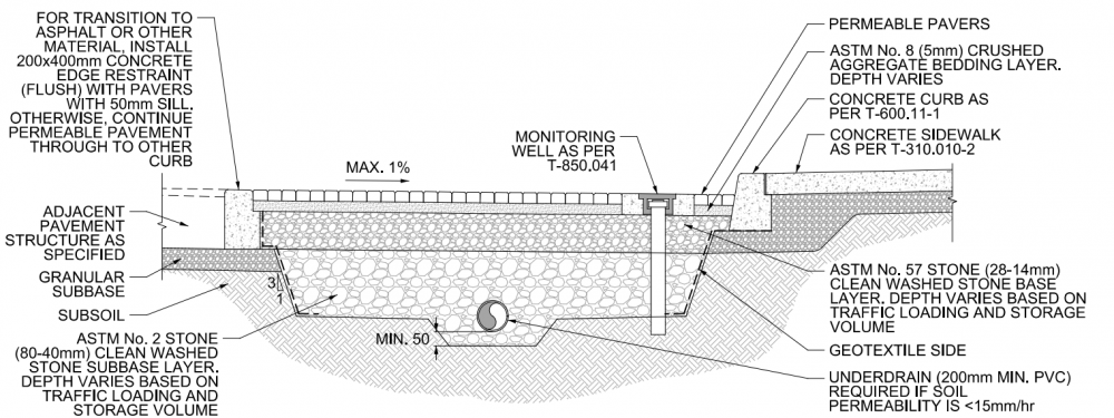
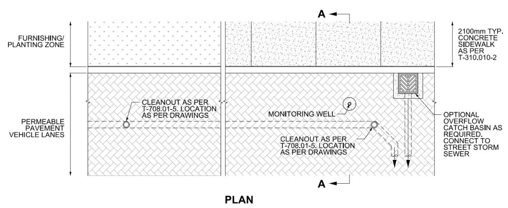
Please see below a profile and plan view of a drawing of a standard permeable pavement composed of interlocking pavers located in a parking lot/laneway (location dependent upon estimated traffic and vehicular loading). The installation is designed with an underdrain in this drawing as the site has low permeability soil (< 15mm/hr), allowing for only partial infiltration in the system. The permeable paver installation also includes a cleanout for said underdrain in case of clogging, and is comprised of a crushed aggregate bedding layer, clean washed stone base, and subbase (more about these layers can be found under here OPSS aggregates & Choker layer). The entire facility is surrounded by a geotextile to retain these layers and separate them from the underlying soil subgrade, allowing the system to infiltrate water into the surrounding soil and prevent migration amongst said layers.
Drawings are from the City of Toronto's, Design Criteria for Green Infrastructure in the Right-of-Way [12] document. For further details about these cross section drawings please visit the link.
Rainwater Harvesting[edit]
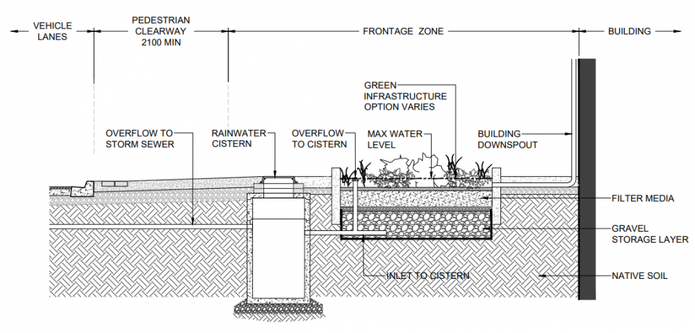
Please see below a profile and plan view of a drawing of a standard rainwater harvesting cistern located on a private/public property's frontage with either a high water table or contaminated subsoils, connected to the building's downspout. This example includes the use of a raingarden as a pretreatment option, along with an underdrain and overflow which both deposit treated rainwater into the holding cistern. If water is not used for irrigation purposes, etc. there is an attached overflow which connects to the municipality's storm sewer system.
Drawings are from the City of Toronto's Green Streets Technical Guidelines Appendices [13] document. For further details about these cross section drawings please visit the link.
Bioswales / Enhanced Swales[edit]
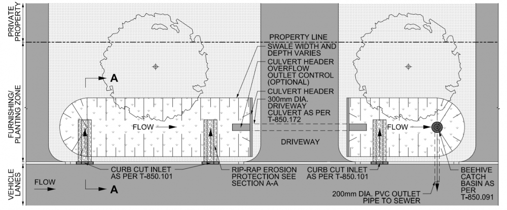
Please find below two sets of profile and plan view drawings of a bioswale and enhanced swale installation. Both installations are located in between the front of a private homeowners' property and the roadway, known as a easement or frontage. The major difference between the two installations is the use of an underdrain for the bioswale, drainage layers, specialized filter media located underneath the geotextile underlain rip-rap so that it provides partial infiltration. Whereas, the enhanced swale provides full infiltration, through a fully vegetated surface, allowing water to travel down slowly to the undisturbed soil substrate below.
Drawings are from the City of Toronto's, Design Criteria for Green Infrastructure in the Right-of-Way [14] document. For further details about these cross section drawings please visit the link.
Stormwater Tree Trenches[edit]
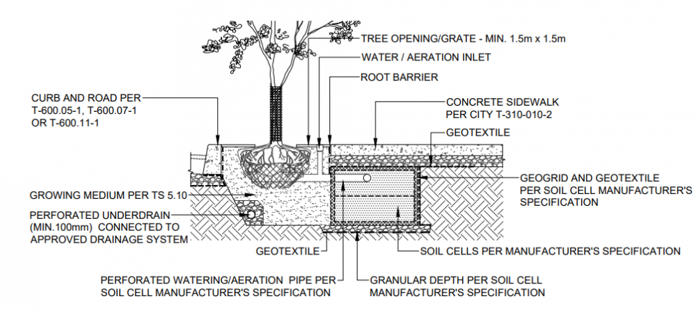
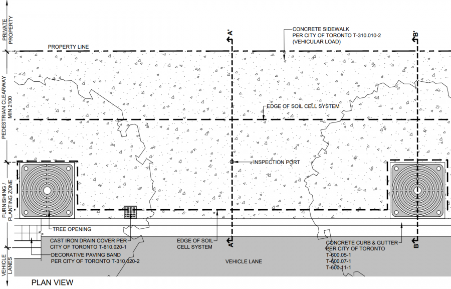
Please see below a plan and profile view of one of several variations of a stormwater planter (soil cell) along a roadway. This type of cross section installment showcases a tree trench in a continuous growing medium located under a hard boulevard/concrete surface that can withstand constant and heavy vehicular loads. Drawings are from the City of Toronto's Green Streets Technical Guidelines Appendices document. For further details about these cross section drawings please visit the link.
Rain Gardens[edit]
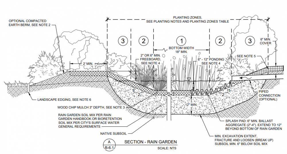
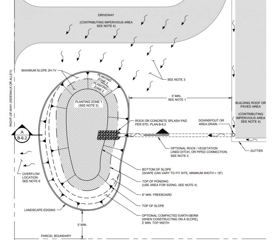
Please see below a plan and profile view of a rain garden, which possesses full infiltration and bioretention functions. In the plan view, note that the contributing area has water coming from both the building's roof, and paved areas, along with the driveway and directed towards the lowest area of the property, where the rain garden is located. This allows the feature to collect and to easily absorb rain and surface water into the ground on homeowners/businesses' properties. The installation also includes a pretreatment rock/concrete forebay to limit erosion and reduce higher velocity flows entering the rain garden, along with mulch, filter media and various planting zones with specific vegetation types that are best suited for these areas within the feature to assist in infiltration and removal of contaminants.
Drawings are from the City of Vancouver's Surface Water/Stormwater Design & Construction Requirements document.[15] For further details about these cross section drawings please visit the link.
External Drawing Cross Sections[edit]
- City of Ottawa - LID Demonstration Project by Aquafor Beech Ltd.
- Oregon State University LID typicals by GreenGirl
- Plan drawings by Low Impact Development Center, Inc.
- Bioretention detail by Philly Water
- Permeable paving by Philly Water
- Pipe-in-stone infiltration by Philly Water
Proprietary[edit]
In our effort to make this guide as functional as possible, we have decided to include proprietary systems and links to manufacturers websites.
Inclusion of such links does not constitute endorsement by the Sustainable Technologies Evaluation Program.
Lists are ordered alphabetically; link updates are welcomed using the form below.
- ADS pipe
- Soil cells by Silvacell
- pretreatment by Hydro International
References[edit]
- ↑ https://www.toronto.ca/services-payments/streets-parking-transportation/enhancing-our-streets-and-public-realm/green-streets/
- ↑ https://www.toronto.ca/services-payments/building-construction/infrastructure-city-construction/construction-standards-permits/standards-for-designing-and-constructing-city-infrastructure/construction-specifications-drawings-for-green-infrastructure/
- ↑ https://www.kitchener.ca/en/development-and-construction/development-manual.aspx
- ↑ https://www.cambridge.ca/en/learn-about/resources/Stormwater-Management-Policy.pdf
- ↑ https://www.barrie.ca/government-news/adopted-strategies-plans/drainage-master-plan
- ↑ https://www.toronto.ca/services-payments/building-construction/infrastructure-city-construction/construction-standards-permits/standards-for-designing-and-constructing-city-infrastructure/construction-specifications-drawings-for-green-infrastructure/?accordion=green-infrastructure-drawings Design Criteria for Green Infrastructure in the Right-of-Way
- ↑ https://sustainabletechnologies.ca/app/uploads/2015/04/UndergroundInfiltrationSystems_TechBrief_April2015.pdf
- ↑ https://www.njstormwater.org/bmp_manual2.htm
- ↑ https://greenactioncentre.ca/healthy-travel/traffic-calming-101/#:~:text=A%20curb%20extension%2C%20or%20curb,to%20reduce%20speed%20(above)
- ↑ https://www.toronto.ca/services-payments/building-construction/infrastructure-city-construction/construction-standards-permits/standards-for-designing-and-constructing-city-infrastructure/construction-specifications-drawings-for-green-infrastructure/?accordion=green-infrastructure-drawings Design Criteria for Green Infrastructure in the Right-of-Way
- ↑ http://www.metrovancouver.org/services/liquid-waste/LiquidWastePublications/StormwaterSourceControlDesignGuidelines2012StormwaterSourceControlDesignGuidelines2012.pdf Stormwater Source Control Design Guidelines
- ↑ https://www.toronto.ca/services-payments/building-construction/infrastructure-city-construction/construction-standards-permits/standards-for-designing-and-constructing-city-infrastructure/construction-specifications-drawings-for-green-infrastructure/?accordion=green-infrastructure-drawings Design Criteria for Green Infrastructure in the Right-of-Way
- ↑ https://www.toronto.ca/services-payments/building-construction/infrastructure-city-construction/construction-standards-permits/standards-for-designing-and-constructing-city-infrastructure/construction-specifications-drawings-for-green-infrastructure/?accordion=green-infrastructure-drawings Design Criteria for Green Infrastructure in the Right-of-Way
- ↑ https://www.toronto.ca/services-payments/building-construction/infrastructure-city-construction/construction-standards-permits/standards-for-designing-and-constructing-city-infrastructure/construction-specifications-drawings-for-green-infrastructure/?accordion=green-infrastructure-drawings Design Criteria for Green Infrastructure in the Right-of-Way
- ↑ https://www.cityofvancouver.us/publicworks/page/surface-waterstormwater-design-construction-requirements

