Difference between revisions of "Wells"
| Line 54: | Line 54: | ||
rect 803 892 1650 1174 [[Filter Media|Filter Media]] | rect 803 892 1650 1174 [[Filter Media|Filter Media]] | ||
| − | rect 803 1180 1650 1323 [[ | + | rect 803 1180 1650 1323 [[Choker layer|Choker Layer (HPB)]] |
rect 800 1326 1650 1489 [[Reservoir aggregate|Clear Stone]] | rect 800 1326 1650 1489 [[Reservoir aggregate|Clear Stone]] | ||
rect 800 737 1656 886 [[Mulch|Mulch]] | rect 800 737 1656 886 [[Mulch|Mulch]] | ||
Revision as of 22:15, 8 December 2021
This article gives tips on the design and installation of monitoring wells into LID practices. It does not address the much deeper wells used to monitor groundwater levels. Monitoring wells are frequently installed on infiltrating systems such as bioretention, bioswales, infiltration trenches and hybrids thereof. The two questions most frequently addressed are:
- How quickly is surface ponding being infiltrated beneath the surface?
- How quickly is the facility draining through exfiltration to native soils and/or through an underdrain?
Shallow wells[edit]
To measure the depth of ponding and the rate at which the ponding water infiltrates, install a shallow well with a water level logger:
- Use a perforated pipe (a piezometer) that will allow surface water to enter the well but will help prevent sediment from accumulating within it.
- Locate the well where ponding occurs first - near the inlet or the lowest point in the feature.
- Measure where the ground surface is relative to where you will be taking your water level measurements.
- Ensure there is a small reservoir in the well to keep your level probe submerged in dry conditions. This practice will also help with calibration.
Deeper wells[edit]
Some LID features are designed to retain water within the media that makes up the LID feature (e.g. permeable pavement will be on top of a gravel bed where water can be stored). To measure the amount of water retention in a monitoring well, install a water level logger:
- Install the well while the feature is being constructed or undergoing major maintenance.
- If there is an underdrain in the feature, make sure the bottom of the well reaches below it.
- Install the well so that surface water will not impact the water level within the well. A standard monitoring well casing over the well pipe should be sufficient.
- If possible, measure the depth of the underdrain. Having this measurement helps determine when water is percolating into the underdrain.
- Ensure there is a small reservoir in the well to keep your level probe submerged in dry conditions.
- Where possible, wells for measuring water levels within permeable pavement systems should be outside of trafficked areas.
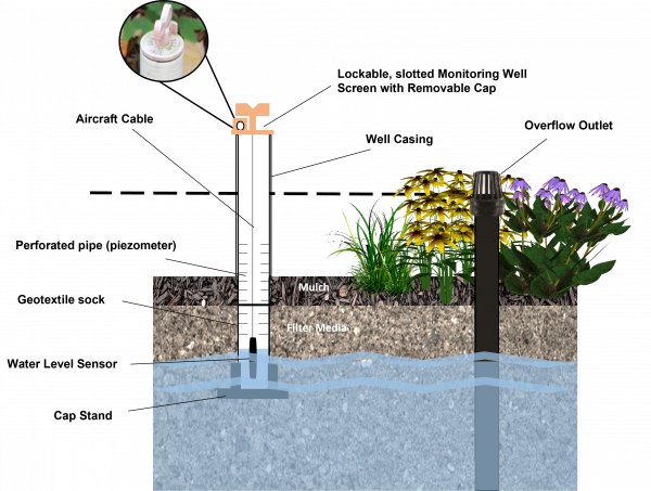
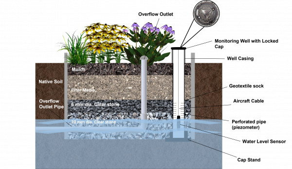
Monitoring Well Specification[edit]
The monitoring well should be installed during construction in a pervious area within the trench between tree planting areas. The well should be vertical from top to bottom.
| Feature | Notes |
|---|---|
| Material | The pipe should be rigid to prevent bending (e.g. PVC). |
| Diameter | minimum 100 mm |
| Perforations | The perforations may be similar spacing similar to underdrain pipes. Perforations are only required on the bottom third of the pipe. The well should be sealed at the surface to prevent short circuiting of surface water flow along the sides of the well. Bentonite clay is often used for this purpose. |
| Sock | The perforated portion of the pipe should be wrapped with a geotextile sock. Standard geotextile provided with perforated pipe may be used. |
| Bottom/sump | The bottom 100 mm of the well should be capped and free of perforations to provide a small reservoir of water to keep the sensor wet during dry weather. |
| Length | The well should extend into the native soil below the facility by a minimum 150 mm. Top should be above the surface overflow elevation or above the maximum ponding depth to prevent surface water from entering the well. If the perforated drainage pipe is installed in a v-notch below the bottom of the facility, the well should extend 150 mm below the invert of this drainage pipe. |
| Cap | The well should be finished with a lockable cap to prevent vandalism. |