Infiltration chambers
Overview[edit]
As their name suggests infiltration galleries work exclusively to infiltrate stormwater. They are an underground facility and are often used beneath parking lots or playing fields to treat flow routed from other areas.
Infiltration galleries are an ideal technology for:
- Installing below any type of surface or landscape
- Receiving and infiltrating large volumes of water
The fundamental components of an infiltration gallery are:
- Structurally reinforced chambers
- Layers of coarse aggregate to bed the chambers and redistribute water.
- Perforated pipe
<panelSuccess>
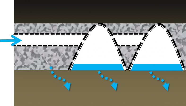
Schematic diagram of an underground infiltration gallery

</panelSuccess>
Design[edit]
Sizing
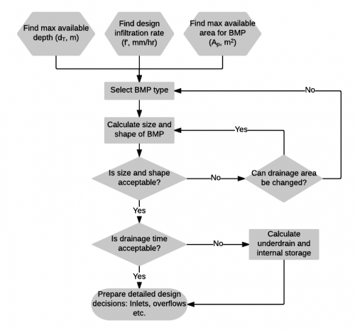
- To calculate the required depth of an infiltration facility in a specified footprint area...
- To calculate the required footprint area of an infiltration facility with a known depth constraint....
- To calculate the drainage time of ponded water on the surface of a facility footprint...
- To calculate the drainage time of an underground infiltration facility...
The sizing calculations require that most of the following parameters be known or estimated. The exceptions are the depth (d) and the permeable footprint area of the practice (Ap), as only one of these is required to find the other. Note that some of these parameters can be limited by site conditions and factors influencing constructability:
- The maximum total depth will be limited by construction practices i.e. usually ≤ 2 m to avoid the need for benching and shoring open cut excavations.
- The maximum total depth may be limited by the conditions underground (e.g. water table or underlying geology/infrastructure).
- The maximum total depth may be limited by the desire to install the practice below the maximum frost penetration depth in the proposed location.
- The maximum total depth may be limited by the desire to support vegetation cover over it (e.g. at least 30 cm of planting soil backfill over the BMP to support grasses)
- Infiltration trenches, chambers and bioretention have a maximum recommended I/P ratio of 20.
| Symbol | Units | Parameter |
|---|---|---|
| D | h | Duration of design storm |
| i | m/h | Intensity of design storm |
| f' | m/h | Design infiltration rate of the underlying native soil, calculated from measured infiltration rate and applied safety factor |
| n | - | Porosity of the aggregate or other void-forming fill material(s) in the storage reservoir of the practice. *Note: For systems that have significant storage in open chambers surrounded by clear stone aggregate, an effective porosity value (n') may be estimated for the whole installation and used in the calculations below. Effective porosity will vary according to the geometry of the storage chambers, so advice should be sought from product manufacturers. Permit applications should include the basis for n' estimates. |
| Ai | m2 | Catchment impervious area |
| dr | m | Water storage reservoir depth. For practices without an underdrain (i.e. full infiltration design), dr is the total depth of the practice (i.e. includes surface ponding and filter media depths). For practices with an underdrain (i.e. partial infiltration design), dr is the depth below the invert of the underdrain perforated pipe or riser pipe upturn. |
| Ap | m2 | Permeable footprint area of the practice. For practices where runoff is directed to a surface ponding area, Ap is the surface ponding area. For practices where runoff is directed to a subsurface water storage reservoir, Ap is the footprint area of the internal water storage reservoir, Ar. |
| x | m | Perimeter of the practice |
| Kf | m/h | Minimum acceptable saturated hydraulic conductivity of the filter media or growing medium (i.e., planting soil) used in the practice, when compacted to 85% maximum dry density |
This spreadsheet tool has been set up to perform all of the infiltration practice sizing calculations shown below
To calculate the required storage reservoir footprint area where the depth is fixed or constrained (1D drainage)[edit]
To ensure that the water storage capacity of the facility is available at the onset of a storm event, it is recommended to size the storage reservoir despth, dr, based on the depth of water that will drain via infiltration between storm events. So dr can be calculated as:
Where
f' = design infiltration rate of the native soil (m/h)
t = drainage time, based on local criteria or long-term average inter-event period for the location (e.g. 72 hr in southern Ontario).
n = Porosity of the stone bed aggregate material (typically 0.4 for 50 mm dia. clear stone)
In many locations there may be a limited depth of soil available above the seasonally high water table or top of bedrock elevation into which stormwater may be infiltrated. In such cases the required storage needs to be distributed more widely across the landscape.
Where the storage reservoir depth is fixed or constrained the footprint area of the water storage reservoir, Ar can be calculated:


To calculate the required storage reservoir depth where the area is fixed or constrained (1D drainage)[edit]
On densely developed sites, the surface area available for the practice may be constrained. In such cases the required storage reservoir depth, dr of the bioretention cell or infiltration trench can be calculated based on available surface area, Ap:
![{\displaystyle d_{r}={\frac {D\left[\left({\frac {Ai}{Ap}}\right)i-f'\right]}{n}}}](https://wikimedia.org/api/rest_v1/media/math/render/svg/109076c0e13275dffcd0342b4035af504fadb12d)
Note that in most cases the results of this calculation will be very similar to those from the equation below assuming three-dimensional drainage.
To calculate the required storage reservoir depth, where the area is fixed or constrained (3D drainage)[edit]
On densely developed sites, the surface area available for the facility may be constrained. In such cases the required water storage reservoir depth of the bioretention cell or infiltration trench, d, can be calculated assuming three-dimensional drainage as follows
![{\displaystyle d_{r}=a[e^{\left(-bD\right)}-1]}](https://wikimedia.org/api/rest_v1/media/math/render/svg/438ecbda65ad748283823ada467a7f5752e09258)
Where

and

(The rearrangement to calculate the required footprint area of the facility for a given depth assuming three-dimensional drainage is not available at this time. Elegant submissions are invited.)
Time required to drain surface ponded water (1D drainage)[edit]
The following equations assume one dimensional drainage over the surface ponding area.
It is best applied to calculate the maximum duration of ponding on the surface of bioretention cells and stormwater tree trenches, and upstream of check dams of bioswales and enhanced grass swales to ensure all surface ponding drains within 24 hours.
To calculate the time (t) to fully drain surface ponded water through the filter media or growing medium:
Where
dp' is the effective or mean surface ponding depth (mm).
Kf is the minimum acceptable saturated hydraulic conductivity of the filter media and growing medium when compacted to 85% maximum dry density (mm/h); minimum of 25 mm/hr is recommended for bioretention filter media; minimum of 15 mm/hr is recommended for enhanced grass swale and stormwater tree trench growing medium.
For full infiltration design practices that do not feature an underdrain, once the internal water storage capacity has been filled, the length of time required to fully drain surface ponded water is limited by the saturated hydraulic conductivity of the underlying in-situ (native) subsoil. To calculate the time (t) to fully drain surface ponded water once filled to capacity:
Where
dp' is the effective or mean surface ponding depth (mm).
f' is the design infiltration rate of the underlying native soil.


Time to drain internal water storage reservoir[edit]
The target drainage time for the internal water storage reservoir portion of an infiltration facility is typically between 48 and 72 hours or based on the average inter-event period for the location. Contact the local municipality or conservation authority for criteria. See Drainage time for more information about how inter-event periods vary across Ontario and to help select what is suitable for the site.
Try the Darcy drainage time calculator tool for estimating the time required to fully drain the water storage reservoir of the facility assuming either one or three-dimensional drainage:

For some geometries, particularly deep or linear facilities, it desirable to account for lateral drainage, out the sides of the storage reservoir.
The following equation makes use of the hydraulic radius (Ar/x), where Ar is the area of the reservoir and x is the perimeter (m) of the reservoir.
Maximizing the perimeter of the water storage reservoir of the facility will enhance drainage performance and directs designers towards longer, linear shapes such as infiltration trenches and bioswales. See illustration for an example.
To calculate the time (t) to fully drain the facility assuming three-dimensional drainage:
Where "ln" means natural logarithm of the term in square brackets
Adapted from CIRIA, The SUDS Manual C753 (2015)[1]
![{\displaystyle t={\frac {n\times A_{r}}{f'\times x}}ln\left[{\frac {\left(d_{r}+{\frac {A_{r}}{x}}\right)}{\left({\frac {A_{r}}{x}}\right)}}\right]}](https://wikimedia.org/api/rest_v1/media/math/render/svg/fd076ebbcacdd842b073815f146a3ad96a66c872)
Materials[edit]
Construction[edit]

Overview[edit]
LID techniques and technologies are new to many municipalities, consulting engineers, and contractors. STEP's construction guidance aims to give practical advice, specific to LID construction, to enable practitioners to successfully construct LID practices.
Common reasons LID projects fail at the construction stage are:
- lack of detail in designs and construction documents
- Contractors can struggle to build LID facilities properly without enough detail in the contract drawings and without guidance and inspection throughout the construction process.
- lack of knowledge
- Designers often do not understand the complexities of the construction process, and contractors often don't understand the purpose of LID practices or the technologies they employ.
- lack of effective erosion and sediment control during construction
- LID practices are most vulnerable to sedimentation and clogging during their own construction or construction of adjacent lands.
- lack of planning and communication
- Poor communication protocols and the pace and extent of construction may preclude proper inspections and certifications.
Published research corroborates STEP’s experiences in the field (e.g., DelGrosso et al., 2019 [2]; LSRCA, 2011[3]; CWP, 2009)[4]). Del Grosso et al. (2019) note that LID requires more considerations during construction compared to traditional stormwater management facilities, and that proper construction of is centered around thoughtful construction sequencing, ensuring all parties involved know their responsibilities, protecting soils and media from compaction and clogging, properly installing filter media and aggregate, and ensuring facilities are kept off-line until the entire drainage area is stabilized.
In short, successful construction of LID practices and treatment trains is dependent on proper training of contractors, project managers and inspectors to ensure they understand the functionality of the practices, the proper timing and sequencing of BMP construction as part of overall site activities, the use of flow diversion, erosion and sediment controls during construction, and the oversight needed to avoid common pitfalls.
Regular inspections throughout the construction process of LID practices prevent end products that are not built to the design specifications. Specifically, they ensure that:
- the LID practice has the proper layout, location, footprint, and volume;
- materials meet design specifications;
- any material substitutions and field changes to the design are verified and documented;
- the contributing drainage area is stabilized before the LID practice becomes operational;
- environmentally sensitive areas and the LID practices themselves are protected during construction; and
- inlet, outlet, pretreatment, and piped elements have the correct elevations and inverts.
Furthermore, keeping records of these inspections helps to certify the works after construction and makes for a smooth assumption process.
Construction stages and LID types[edit]

STEP divides the construction process for LID practices into five overarching stages:
- Pre-construction
- Excavation and grading
- Sub-surface components
- Finishing grades and surface layer installation: vegetated LIDs and finishing grades and surface layer installation: permeable pavements, and
- Post-construction
Most LID practices work at the sub-surface and ground-level by routing stormwater flows from impervious surfaces into excavated or natural depressions or by allowing stormwater to pass through a pervious surface, as is the case with permeable pavements. These depressions are designed and constructed to the meet goals of the LID practice, which may be quality control, quantity control, or water balance restoration. Bioretention gardens, stormwater planters, bioswales, rain gardens, enhanced swales, exfiltration trenches, permeable pavements, infiltration systems (chambers, trenches, and soakaways), and stormwater tree trenches fall into this category.
For this reason, Stages 1-2 and 5 of the LID construction process are fundamentally similar for all sub-surface and ground-level LID types. To illustrate, STEP's recommended processes for excavation do not differ between LID practice types. Excavation procedures are the same, whether for a bioretention garden or a permeable pavement parking lot. On the other hand, stage 4 sub-tasks will vary depending on whether the LID practice's surface is vegetated or permeable pavement. Some sub-tasks in stage 3 will also vary depending on the LID type. For example, permeable pavements often require compaction of sub-surface storage layers. The following sections give a brief description of each over-arching stage, a list of sub-tasks for each stage, and links to the page dedicated to each main LID construction stage.
STEP has developed practice-specific construction inspection checklists for bioretention and bioswales, permeable pavement, enhanced swales, vegetated filter strips, underground infiltration systems (exfiltration systems, trenches, chambers, soakaways), green roofs, and rainwater harvesting.
Green roofs and rainwater harvesting systems have specific construction sequences and requirements that differ from the main sequence described above. STEP has developed guidance for green roof construction; guidance on installing rainwater harvesting practices is forthcoming. When installing these BMP types, always consult the product manufacturer's guidance.
Pre-construction[edit]
Pre-construction activities set the stage for the successful construction of an LID practice. The pre-construction page gives guidance on:
- design verification and site walk-through
- LID construction notes
- tendering and contract
- communication, inspection plan, and utilities coordination
- erosion and sediment control measures
- mobilization, access, staging, and perimeter controls
Excavation and grading[edit]

Excavation and grading are necessary for installing LID practices with sub-surface components, re-grading land to hold more water, and re-routing overland flow routes into an LID practice. The excavation and grading page gives guidance on:
- clearing and grubbing
- excavation and rough grade
- sub-grade
- final excavated grade and verification
Sub-surface components[edit]
Most LID practices use a combination of sub-surface features such as gravel storage reservoirs, liners, underdrains, monitoring wells, and other components to meet their design objectives. The construction process for sub-surface components works from the ground up. While some LID practices include all the sub-surface components listed below, most designs will not include one or more of these layers or components. Permeable pavements can have different construction requirements at this stage, mostly regarding compaction of sub-surface layers. Installing infiltration chambers also requires guidance specific to that LID type. Stormwater Tree Trenches, which consist of subsurface trenches filled with modular structures and growing medium, or structurally engineered soil medium to supporting an overlying pavements, also require advice specific to them.
The sub-surface components page gives guidance on:
- geotextile
- underdrain
- impermeable liner
- overflow
- monitoring wells
- storage reservoir
- sub-base reservoir (permeable pavements)
- base course (permeable pavements)
- infiltration chambers
- choker layer
- curbing and curb cuts
- pretreatment and inlets
Finishing grades and surface layer installation[edit]

This construction stage differs between LID practice type. The finishing grades and surface layer installation: vegetated LIDs page has guidance for vegetated LIDs, and the finishing grades and surface layer installation: permeable pavements page has guidance for and non-vegetated LIDs. In many cases the surface of infiltration systems will be traditional asphalt, concrete, or pavers; STEP does not provide guidance on installing non-permeable surfaces.
| LID practices with vegetated surfaces | Permeable pavements |
|---|---|
| soil media installation and soil amendments | bedding layer |
| finish grading | placement and finishing |
| large stone and riprap | paver installation |
| plant verification and installation | tamping |
| mulch placement | joint cutting |
| stabilizing contributing drainage area and planting adjacent vegetation | joint aggregate |
| -- | curbing |
| -- | stabilizing contributing drainage area |
Post-construction[edit]
Post-construction tasks ensure that the LID practice was built to specs and that any outstanding issues with it are resolved before assumption. The post-construction page give guidance on:
- Addressing deficiencies
- Final certification
References[edit]
- REDIRECT Special:ArticleFeedbackv5
- ↑ Construction Industry Research and Information Association (CIRIA). 2015. The SUDS Manual C753. Accessed: 18 November 2021. https://www.ciria.org/CIRIA/Memberships/The_SuDs_Manual_C753_Chapters.aspx
- ↑ Delgrosso, Z.L., Clayton, C.H., Dymond, R.L. 2019 Identifying Key Factors for Implementation and Maintenance of Green Stormwater Infrastruture. Journal of Sustainable Water in the Built Environment. 5 (3): 05019002. https://ascelibrary.org/doi/10.1061/JSWBAY.0000878
- ↑ Lake Simcoe Region Conservation Authority (LSRCA). 2011. Stormwater Pond Maintenance and Anoxic Conditions Investigation. Final Report. Newmarket, ON. https://sustainabletechnologies.ca/app/uploads/2015/01/LSRCA-Stormwater-Maintenance-and-Anoxic-Conditions-2011.pdf
- ↑ Centre for Watershed Protection. 2009. Technical Report Stormwater BMPs in Virginia’s James River Basin: An Assessment of Field Conditions & Programs (part of the Extreme BMP Makeover project). Prepared by David Hirschman, Laurel Woodworth, and Sadie Drescher Center for Watershed Protection, Inc. Final Draft. June 2009. https://www.chesapeakebay.net/channel_files/19219/cwp_james_river_tech_report_final_draft_062509.pdf.pdf