Difference between revisions of "Infiltration: Sizing and modeling"
Jenny Hill (talk | contribs) |
|||
| (240 intermediate revisions by 4 users not shown) | |||
| Line 1: | Line 1: | ||
| − | < | + | __NOTOC__ |
| − | < | + | <imagemap> |
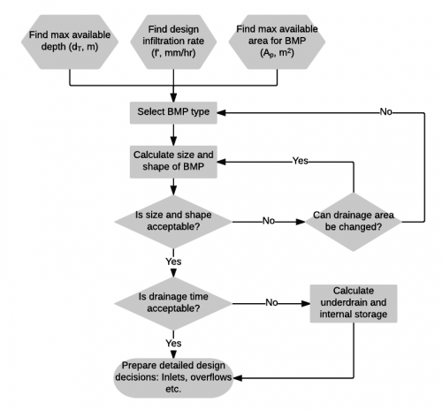
| + | Image:Infiltration.png|thumb|500 px|This is an image map; clicking on components will load the appropriate article. | ||
| + | poly 315 507 208 555 317 605 423 555 [[Drainage time]] | ||
| + | rect 210 658 426 730 [[Details]] | ||
| + | rect 568 522 728 594 [[Underdrain]] | ||
| + | poly 73 27 39 75 75 126 179 126 215 78 181 27 [[Infiltration]] | ||
| + | poly 268 25 235 75 270 123 364 124 395 76 365 25 [[Infiltration: Testing]] | ||
| + | rect 237 185 397 225 [[Select BMP type]] | ||
| + | rect 238 266 397 329 [[Bioretention: Sizing]] | ||
| + | </imagemap> | ||
| + | {{textbox| | ||
| + | {{plainlist| | ||
| + | *To calculate the required depth of an infiltration facility in a specified footprint area... | ||
| + | *To calculate the required footprint area of an infiltration facility with a known depth constraint.... | ||
| + | *To calculate the drainage time of ponded water on the surface of a facility footprint... | ||
| + | *To calculate the drainage time of an underground infiltration facility...|}}}} | ||
| + | |||
| + | The sizing calculations require that most of the following parameters be known or estimated. | ||
| + | The exceptions are the depth (''d'') and the permeable footprint area of the practice (''Ap''), as only one of these is required to find the other. | ||
| + | Note that some of these parameters can be limited by site conditions and factors influencing constructability: | ||
| + | #The ''maximum'' total depth will be limited by construction practices i.e. usually ≤ 2 m to avoid the need for benching and shoring open cut excavations. | ||
| + | #The ''maximum'' total depth may be limited by the [[Infiltration| conditions underground]] (e.g. water table or underlying geology/infrastructure). | ||
| + | #The ''maximum'' total depth may be limited by the desire to install the practice below the maximum frost penetration depth in the proposed location. | ||
| + | #The ''maximum'' total depth may be limited by the desire to support vegetation cover over it (e.g. at least 30 cm of planting soil backfill over the BMP to support grasses) | ||
| + | #[[Infiltration trenches]], [[Infiltration chambers| chambers]] and [[bioretention]] have a maximum recommended I/P ratio of 20. | ||
| + | |||
| + | {|class="wikitable" | ||
| + | |+ Inputs | ||
| + | |- | ||
| + | !style="background: darkcyan; color: white"|Symbol | ||
| + | !style="background: darkcyan; color: white"|Units | ||
| + | !style="background: darkcyan; color: white"|Parameter | ||
| + | |- | ||
| + | |''D''||h||Duration of design storm | ||
| + | |- | ||
| + | |''i''||m/h||Intensity of design storm | ||
| + | |- | ||
| + | |''f'''||m/h||[[Design infiltration rate]] of the underlying native soil, calculated from measured [[Infiltration: Testing| infiltration rate]] and applied [[Infiltration|safety factor]] | ||
| + | |- | ||
| + | |''n''||-||Porosity of the aggregate or other void-forming fill material(s) in the storage reservoir of the practice.<br> *Note: For systems that have significant storage in open chambers surrounded by clear stone aggregate, an effective porosity value (''n<nowiki>'</nowiki>'') may be estimated for the whole installation and used in the calculations below. Effective porosity will vary according to the geometry of the storage chambers, so advice should be sought from product manufacturers. Permit applications should include the basis for ''n<nowiki>'</nowiki>'' estimates. | ||
| + | |- | ||
| + | |''A<sub>i''||m<sup>2</sup>||Catchment impervious area | ||
| + | |- | ||
| + | |''d<sub>r</sub>''||m||Water storage reservoir depth. For practices without an underdrain (i.e. full infiltration design), d<sub>r</sub> is the total depth of the practice (i.e. includes surface ponding and filter media depths). For practices with an underdrain (i.e. partial infiltration design), d<sub>r</sub> is the depth below the invert of the underdrain perforated pipe or riser pipe upturn. | ||
| + | |- | ||
| + | |''A<sub>p</sub>''||m<sup>2</sup>||Permeable footprint area of the practice. For practices where runoff is directed to a surface ponding area, A<sub>p</sub> is the surface ponding area. For practices where runoff is directed to a subsurface water storage reservoir, A<sub>p</sub> is the footprint area of the internal water storage reservoir, A<sub>r</sub>. | ||
| + | |- | ||
| + | |''x''||m||Perimeter of the practice | ||
| + | |- | ||
| + | |''K<sub>f</sub>''||m/h||Minimum acceptable saturated hydraulic conductivity of the [[Bioretention: Filter media|filter media]] or growing medium (i.e., planting soil) used in the practice, when compacted to 85% maximum dry density | ||
| + | |} | ||
| + | |||
| + | This spreadsheet tool has been set up to perform all of the infiltration practice sizing calculations shown below<br> | ||
| + | {{Clickable button|[[Media:Infiltration Sizing 20220617 locked (1).xlsx|Download the infiltration practice sizing tool]]}} | ||
| + | |||
| + | ==To calculate the required storage reservoir footprint area where the depth is fixed or constrained (1D drainage)== | ||
| + | To ensure that the water storage capacity of the facility is available at the onset of a storm event, it is recommended to size the storage reservoir despth, d<sub>r</sub>, based on the depth of water that will drain via infiltration between storm events. So d<sub>r</sub> can be calculated as:<br> | ||
| + | <math>d_{r} = \frac{f'\times t}{n} </math> | ||
| + | Where <br> | ||
| + | ''f''' = [[design infiltration rate]] of the native soil (m/h) <br> | ||
| + | ''t'' = [[drainage time]], based on local criteria or long-term average inter-event period for the location (e.g. 72 hr in southern Ontario).<br> | ||
| + | ''n'' = Porosity of the stone bed aggregate material (typically 0.4 for 50 mm dia. [[reservoir aggregate|clear stone]]) | ||
<br> | <br> | ||
| − | < | + | In many locations there may be a limited depth of soil available above the seasonally high water table or top of bedrock elevation into which stormwater may be infiltrated. In such cases the required storage needs to be distributed more widely across the landscape. <br> |
| − | + | Where the storage reservoir depth is fixed or constrained the footprint area of the water storage reservoir, A<sub>r</sub> can be calculated: | |
| − | + | <math>A_{r}=\frac{i \times D \times Ai}{(n\times d_{r})+f'D}</math> | |
| − | + | ||
| − | + | ==To calculate the required storage reservoir depth where the area is fixed or constrained (1D drainage)== | |
| − | + | On densely developed sites, the surface area available for the practice may be constrained. In such cases the required storage reservoir depth, d<sub>r</sub> of the bioretention cell or infiltration trench can be calculated based on available surface area, A<sub>p</sub>: | |
| − | </ | + | :<math>d_{r}=\frac{D\left[\left( \frac{Ai}{Ap} \right )i-f' \right]}{n}</math> |
| − | < | + | Note that in most cases the results of this calculation will be very similar to those from the equation below assuming three-dimensional drainage. |
| − | + | ||
| − | + | ==To calculate the required storage reservoir depth, where the area is fixed or constrained (3D drainage)== | |
| − | + | On densely developed sites, the surface area available for the facility may be constrained. In such cases the required water storage reservoir depth of the bioretention cell or infiltration trench, d, can be calculated assuming three-dimensional drainage as follows | |
| − | + | :<math>d_{r}=a[e^{\left ( -bD \right )} -1]</math> | |
| − | + | Where | |
| − | < | + | :<math>a=\frac{A_{r}}{x}-\frac{i\times A_{i}}{x\times f'}</math> |
| − | + | and <br> | |
| − | <p> | + | :<math>b=\frac{x\times f'}{n\times A_{r}}</math> |
| − | < | + | |
| − | + | (The rearrangement to calculate the required footprint area of the facility for a given depth assuming three-dimensional drainage is not available at this time. Elegant submissions are invited.)<br> | |
| − | + | <br> | |
| − | + | ||
| − | + | ==Time required to drain surface ponded water (1D drainage)== | |
| − | + | The following equations assume one dimensional drainage over the surface ponding area. | |
| − | < | + | It is best applied to calculate the maximum duration of ponding on the surface of [[Bioretention |bioretention cells]] and [[Stormwater Tree Trenches |stormwater tree trenches]], and upstream of check dams of [[bioswales]] and [[enhanced grass swales]] to ensure all surface ponding drains within 24 hours.<br> |
| − | < | + | To calculate the time (''t'') to fully drain surface ponded water through the filter media or growing medium: |
| − | + | <math>t=\frac{d_{p}'}{K_{f}}</math> <br> | |
| + | Where <br> | ||
| + | d<sub>p</sub>' is the effective or mean surface ponding depth (mm).<br> | ||
| + | K<sub>f</sub> is the minimum acceptable saturated hydraulic conductivity of the filter media and growing medium when compacted to 85% maximum dry density (mm/h); minimum of 25 mm/hr is recommended for bioretention filter media; minimum of 15 mm/hr is recommended for enhanced grass swale and stormwater tree trench growing medium.<br> | ||
| + | <br> | ||
| + | For full infiltration design practices that do not feature an underdrain, once the internal water storage capacity has been filled, the length of time required to fully drain surface ponded water is limited by the saturated hydraulic conductivity of the underlying in-situ (native) subsoil. To calculate the time (''t'') to fully drain surface ponded water once filled to capacity: | ||
| + | <math>t=\frac{d_{p}'}{f'}</math> <br> | ||
| + | Where <br> | ||
| + | d<sub>p</sub>' is the effective or mean surface ponding depth (mm).<br> | ||
| + | f' is the design infiltration rate of the underlying native soil. | ||
| + | |||
| + | ==Time to drain internal water storage reservoir== | ||
| + | The target [[drainage time]] for the internal water storage reservoir portion of an infiltration facility is typically between 48 and 72 hours or based on the average inter-event period for the location. Contact the local municipality or conservation authority for criteria. See [[Drainage time]] for more information about how inter-event periods vary across Ontario and to help select what is suitable for the site. <br> | ||
| + | <br> | ||
| + | Try the Darcy drainage time calculator tool for estimating the time required to fully drain the water storage reservoir of the facility assuming either one or three-dimensional drainage: <br> | ||
| + | {{Clickable button|[[Media:Darcy drainage 20200528 locked.xlsx|Download the Darcy drainage time calculator]]}}<br> | ||
| + | <br> | ||
| + | [[file:Hydraulic radius.png|thumb|Three footprint areas of 9 m<sup>2</sup>.<br> | ||
| + | From left to right x = 12 m, x = 20 m]]<br> | ||
| + | For some geometries, particularly deep or linear facilities, it desirable to account for lateral drainage, out the sides of the storage reservoir. | ||
| + | The following equation makes use of the hydraulic radius (''A<sub>r</sub>''/''x''), where ''A<sub>r</sub>'' is the area of the reservoir and ''x'' is the perimeter (m) of the reservoir. <br> | ||
| + | |||
| + | '''Maximizing the perimeter of the water storage reservoir of the facility will enhance drainage performance and directs designers towards longer, linear shapes such as [[infiltration trenches]] and [[bioswales]].''' See illustration for an example.<br> | ||
| + | To calculate the time (''t'') to fully drain the facility assuming three-dimensional drainage: | ||
| + | <math>t=\frac{n\times A_{r}}{f'\times x}ln\left [ \frac{\left (d_{r} + \frac{A_{r}}{x} \right)}{\left (\frac{A_{r}}{x}\right) }\right]</math> | ||
| + | Where "ln" means natural logarithm of the term in square brackets <br> | ||
| + | Adapted from CIRIA, The SUDS Manual C753 (2015)<ref>Construction Industry Research and Information Association (CIRIA). 2015. The SUDS Manual C753. Accessed: 18 November 2021. https://www.ciria.org/CIRIA/Memberships/The_SuDs_Manual_C753_Chapters.aspx</ref> | ||
| + | |||
[[category: modeling]] | [[category: modeling]] | ||
| + | [[category: infiltration]] | ||
Latest revision as of 19:14, 6 October 2022
- To calculate the required depth of an infiltration facility in a specified footprint area...
- To calculate the required footprint area of an infiltration facility with a known depth constraint....
- To calculate the drainage time of ponded water on the surface of a facility footprint...
- To calculate the drainage time of an underground infiltration facility...
The sizing calculations require that most of the following parameters be known or estimated. The exceptions are the depth (d) and the permeable footprint area of the practice (Ap), as only one of these is required to find the other. Note that some of these parameters can be limited by site conditions and factors influencing constructability:
- The maximum total depth will be limited by construction practices i.e. usually ≤ 2 m to avoid the need for benching and shoring open cut excavations.
- The maximum total depth may be limited by the conditions underground (e.g. water table or underlying geology/infrastructure).
- The maximum total depth may be limited by the desire to install the practice below the maximum frost penetration depth in the proposed location.
- The maximum total depth may be limited by the desire to support vegetation cover over it (e.g. at least 30 cm of planting soil backfill over the BMP to support grasses)
- Infiltration trenches, chambers and bioretention have a maximum recommended I/P ratio of 20.
| Symbol | Units | Parameter |
|---|---|---|
| D | h | Duration of design storm |
| i | m/h | Intensity of design storm |
| f' | m/h | Design infiltration rate of the underlying native soil, calculated from measured infiltration rate and applied safety factor |
| n | - | Porosity of the aggregate or other void-forming fill material(s) in the storage reservoir of the practice. *Note: For systems that have significant storage in open chambers surrounded by clear stone aggregate, an effective porosity value (n') may be estimated for the whole installation and used in the calculations below. Effective porosity will vary according to the geometry of the storage chambers, so advice should be sought from product manufacturers. Permit applications should include the basis for n' estimates. |
| Ai | m2 | Catchment impervious area |
| dr | m | Water storage reservoir depth. For practices without an underdrain (i.e. full infiltration design), dr is the total depth of the practice (i.e. includes surface ponding and filter media depths). For practices with an underdrain (i.e. partial infiltration design), dr is the depth below the invert of the underdrain perforated pipe or riser pipe upturn. |
| Ap | m2 | Permeable footprint area of the practice. For practices where runoff is directed to a surface ponding area, Ap is the surface ponding area. For practices where runoff is directed to a subsurface water storage reservoir, Ap is the footprint area of the internal water storage reservoir, Ar. |
| x | m | Perimeter of the practice |
| Kf | m/h | Minimum acceptable saturated hydraulic conductivity of the filter media or growing medium (i.e., planting soil) used in the practice, when compacted to 85% maximum dry density |
This spreadsheet tool has been set up to perform all of the infiltration practice sizing calculations shown below
To calculate the required storage reservoir footprint area where the depth is fixed or constrained (1D drainage)[edit]
To ensure that the water storage capacity of the facility is available at the onset of a storm event, it is recommended to size the storage reservoir despth, dr, based on the depth of water that will drain via infiltration between storm events. So dr can be calculated as:
Where
f' = design infiltration rate of the native soil (m/h)
t = drainage time, based on local criteria or long-term average inter-event period for the location (e.g. 72 hr in southern Ontario).
n = Porosity of the stone bed aggregate material (typically 0.4 for 50 mm dia. clear stone)
In many locations there may be a limited depth of soil available above the seasonally high water table or top of bedrock elevation into which stormwater may be infiltrated. In such cases the required storage needs to be distributed more widely across the landscape.
Where the storage reservoir depth is fixed or constrained the footprint area of the water storage reservoir, Ar can be calculated:


To calculate the required storage reservoir depth where the area is fixed or constrained (1D drainage)[edit]
On densely developed sites, the surface area available for the practice may be constrained. In such cases the required storage reservoir depth, dr of the bioretention cell or infiltration trench can be calculated based on available surface area, Ap:
![{\displaystyle d_{r}={\frac {D\left[\left({\frac {Ai}{Ap}}\right)i-f'\right]}{n}}}](https://wikimedia.org/api/rest_v1/media/math/render/svg/109076c0e13275dffcd0342b4035af504fadb12d)
Note that in most cases the results of this calculation will be very similar to those from the equation below assuming three-dimensional drainage.
To calculate the required storage reservoir depth, where the area is fixed or constrained (3D drainage)[edit]
On densely developed sites, the surface area available for the facility may be constrained. In such cases the required water storage reservoir depth of the bioretention cell or infiltration trench, d, can be calculated assuming three-dimensional drainage as follows
![{\displaystyle d_{r}=a[e^{\left(-bD\right)}-1]}](https://wikimedia.org/api/rest_v1/media/math/render/svg/438ecbda65ad748283823ada467a7f5752e09258)
Where

and

(The rearrangement to calculate the required footprint area of the facility for a given depth assuming three-dimensional drainage is not available at this time. Elegant submissions are invited.)
Time required to drain surface ponded water (1D drainage)[edit]
The following equations assume one dimensional drainage over the surface ponding area.
It is best applied to calculate the maximum duration of ponding on the surface of bioretention cells and stormwater tree trenches, and upstream of check dams of bioswales and enhanced grass swales to ensure all surface ponding drains within 24 hours.
To calculate the time (t) to fully drain surface ponded water through the filter media or growing medium:
Where
dp' is the effective or mean surface ponding depth (mm).
Kf is the minimum acceptable saturated hydraulic conductivity of the filter media and growing medium when compacted to 85% maximum dry density (mm/h); minimum of 25 mm/hr is recommended for bioretention filter media; minimum of 15 mm/hr is recommended for enhanced grass swale and stormwater tree trench growing medium.
For full infiltration design practices that do not feature an underdrain, once the internal water storage capacity has been filled, the length of time required to fully drain surface ponded water is limited by the saturated hydraulic conductivity of the underlying in-situ (native) subsoil. To calculate the time (t) to fully drain surface ponded water once filled to capacity:
Where
dp' is the effective or mean surface ponding depth (mm).
f' is the design infiltration rate of the underlying native soil.


Time to drain internal water storage reservoir[edit]
The target drainage time for the internal water storage reservoir portion of an infiltration facility is typically between 48 and 72 hours or based on the average inter-event period for the location. Contact the local municipality or conservation authority for criteria. See Drainage time for more information about how inter-event periods vary across Ontario and to help select what is suitable for the site.
Try the Darcy drainage time calculator tool for estimating the time required to fully drain the water storage reservoir of the facility assuming either one or three-dimensional drainage:

For some geometries, particularly deep or linear facilities, it desirable to account for lateral drainage, out the sides of the storage reservoir.
The following equation makes use of the hydraulic radius (Ar/x), where Ar is the area of the reservoir and x is the perimeter (m) of the reservoir.
Maximizing the perimeter of the water storage reservoir of the facility will enhance drainage performance and directs designers towards longer, linear shapes such as infiltration trenches and bioswales. See illustration for an example.
To calculate the time (t) to fully drain the facility assuming three-dimensional drainage:
Where "ln" means natural logarithm of the term in square brackets
Adapted from CIRIA, The SUDS Manual C753 (2015)[1]
![{\displaystyle t={\frac {n\times A_{r}}{f'\times x}}ln\left[{\frac {\left(d_{r}+{\frac {A_{r}}{x}}\right)}{\left({\frac {A_{r}}{x}}\right)}}\right]}](https://wikimedia.org/api/rest_v1/media/math/render/svg/fd076ebbcacdd842b073815f146a3ad96a66c872)
- ↑ Construction Industry Research and Information Association (CIRIA). 2015. The SUDS Manual C753. Accessed: 18 November 2021. https://www.ciria.org/CIRIA/Memberships/The_SuDs_Manual_C753_Chapters.aspx