Difference between revisions of "Overflow"
Jenny Hill (talk | contribs) m (→Options) |
Dean Young (talk | contribs) |
||
| (31 intermediate revisions by 5 users not shown) | |||
| Line 1: | Line 1: | ||
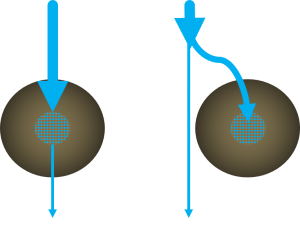
[[File:Routing.png|thumb|Conceptual diagram of the excess routing alternatives: On the left, excess flow leaves the cell via an overflow; on the right, excess flow is diverted so that only the design volume enters the cell.]] | [[File:Routing.png|thumb|Conceptual diagram of the excess routing alternatives: On the left, excess flow leaves the cell via an overflow; on the right, excess flow is diverted so that only the design volume enters the cell.]] | ||
| − | ==Routing== | + | ===Routing=== |
| − | *Infiltration facilities can be designed to be inline or offline from the drainage system. See | + | *Infiltration facilities can be designed to be inline or offline from the drainage system. See figure to the right for an illustration. |
| − | *Inline facilities accept all of the flow from a drainage area and convey larger event flows through an overflow outlet. The overflow must be sized to safely convey larger storm events out of the facility. | + | *Inline facilities accept all of the flow from a drainage area and convey larger event flows through an overflow outlet. The overflow must be sized to safely convey larger storm events out of the facility. The overflow must be situated at the maximum surface ponding elevation or furthest downgradient end of the facility to limit surface ponding during periods of flow in excess of the facility storage capacity. |
| − | + | *Offline facilities use flow splitters or bypass channels that only allow the design storm runoff storage volume to enter the facility. Higher flows are conveyed to a downstream storm sewer or other BMP by a flow splitting manhole weir or pipe, or when the maximum surface ponding depth has been reached, by by-passing the curb opening and flowing into a downstream catchbasin connected to a storm sewer. | |
| − | *Offline facilities use flow splitters or bypass channels that only allow the | ||
| − | |||
| − | ==Options== | + | ===Overflow Elevation=== |
| + | The invert of the overflow should be placed at the maximum water surface elevation of the practice (i.e. the maximum surface ponding level). | ||
| + | A good starting point is 150 to 350 mm above the surface of the mulch cover. However, consideration should be given to public safety, whether or not an underdrain is included, the time required for ponded water to drain through the filter bed surface, and if no underdrain is present, into the underlying native soil (must drain within 48 hours). | ||
| + | See [[Bioretention: Sizing]] and [[Stormwater planters]] for more details. | ||
| + | |||
| + | ===Freeboard=== | ||
| + | {{:freeboard}} | ||
| + | |||
| + | ===Overflow Outlet Options=== | ||
Metal grates are recommended (over plastic) in all situations. | Metal grates are recommended (over plastic) in all situations. | ||
| Line 36: | Line 42: | ||
| x | | x | ||
|- | |- | ||
| − | | Curb cut | + | | [[Curb cut]] |
| x | | x | ||
| x | | x | ||
| Line 42: | Line 48: | ||
|} | |} | ||
| − | ==Gallery== | + | ===Gallery=== |
{{:Overflow:Gallery}} | {{:Overflow:Gallery}} | ||
Latest revision as of 15:46, 6 April 2022
Routing[edit]
- Infiltration facilities can be designed to be inline or offline from the drainage system. See figure to the right for an illustration.
- Inline facilities accept all of the flow from a drainage area and convey larger event flows through an overflow outlet. The overflow must be sized to safely convey larger storm events out of the facility. The overflow must be situated at the maximum surface ponding elevation or furthest downgradient end of the facility to limit surface ponding during periods of flow in excess of the facility storage capacity.
- Offline facilities use flow splitters or bypass channels that only allow the design storm runoff storage volume to enter the facility. Higher flows are conveyed to a downstream storm sewer or other BMP by a flow splitting manhole weir or pipe, or when the maximum surface ponding depth has been reached, by by-passing the curb opening and flowing into a downstream catchbasin connected to a storm sewer.
Overflow Elevation[edit]
The invert of the overflow should be placed at the maximum water surface elevation of the practice (i.e. the maximum surface ponding level). A good starting point is 150 to 350 mm above the surface of the mulch cover. However, consideration should be given to public safety, whether or not an underdrain is included, the time required for ponded water to drain through the filter bed surface, and if no underdrain is present, into the underlying native soil (must drain within 48 hours). See Bioretention: Sizing and Stormwater planters for more details.
Freeboard[edit]
- In swales conveying flowing water a freeboard of 300 mm is generally accepted as a good starting point.
- In bioretention the freeboard is the difference between the invert elevation of the inlet and overflow structure. 150 mm will usually suffice, so long as the inlet will not become inundated during design storm conditions.
- In above grade stormwater planters, the equivalent dimension would be the difference between the invert elevation of the lip of the planter and the overflow structure (150 mm minimum).
Overflow Outlet Options[edit]
Metal grates are recommended (over plastic) in all situations.
| Feature | Anti Vandalism/Robust | Lower Cost Option | Self cleaning |
|---|---|---|---|
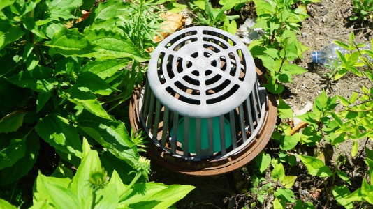
| Dome grate | x | ||
| Flat grate | x | ||
| Catch basin | x | ||
| Ditch inlet catch basin | x | x | |
| Curb cut | x | x | x |
Gallery[edit]
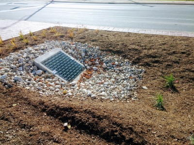
Flat metal overflow with stone surround to reduce erosion around the cast concrete structure. Mississauga Road, ON
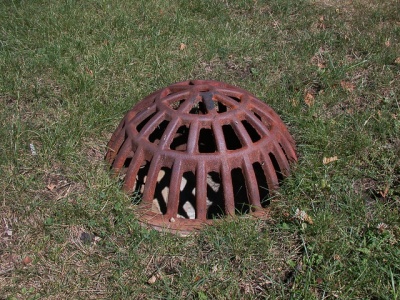
Domed, metal overflow grate. Being flush with the surface reduces potential infiltration of ponded water. Photo credit: Aaron Volkening
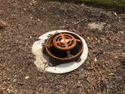
Overflow inlet for newly constructed stormwater bioretention areas in median of Bradley Road. Village of Brown Deer, Wisconsin. Bradley Road, east of 51st Street. Photo from October 2015. Constructed summer 2015.
Photo credit: Aaron Volkening
