Difference between revisions of "Swales"
Jenny Hill (talk | contribs) (→Design) |
Jenny Hill (talk | contribs) (→Design) |
||
| Line 75: | Line 75: | ||
<p>To minimize erosion and maximize the functionality of the swale, sheet flow of surface water should be directed into the side of the BMP. [[Vegetated filter strips]] and shallow side slopes are ideal. Alternatively, a series of curb inlets can be employed, where each has some form of flow spreading incorporated. Single point inflow can cause increased erosion and sedimentation which will damage vegetation and contribute to BMP failure. Again, flow spreading devices can mitigate these processes, where concentrated point inflow is required. </p> | <p>To minimize erosion and maximize the functionality of the swale, sheet flow of surface water should be directed into the side of the BMP. [[Vegetated filter strips]] and shallow side slopes are ideal. Alternatively, a series of curb inlets can be employed, where each has some form of flow spreading incorporated. Single point inflow can cause increased erosion and sedimentation which will damage vegetation and contribute to BMP failure. Again, flow spreading devices can mitigate these processes, where concentrated point inflow is required. </p> | ||
<h4>Underdrains</h4> | <h4>Underdrains</h4> | ||
| − | |||
<ul> | <ul> | ||
<li>Underdrains should be constructed from perforated plastic (PVC or HDPE, between 100 - 200 mm). The larger 200 mm diameter is recommended to address any concerns about freezing conditions. </li> | <li>Underdrains should be constructed from perforated plastic (PVC or HDPE, between 100 - 200 mm). The larger 200 mm diameter is recommended to address any concerns about freezing conditions. </li> | ||
| Line 81: | Line 80: | ||
<li>The drain should be embedded into a coarse gravel layer, with a minimum of 100 mm aggregate below the pipe and 150 mm aggregate above. the pipe. To reduce the potential for sediment clogging the pipe, the gravel layer should be overlaid with a geotextile filter fabric. </li> | <li>The drain should be embedded into a coarse gravel layer, with a minimum of 100 mm aggregate below the pipe and 150 mm aggregate above. the pipe. To reduce the potential for sediment clogging the pipe, the gravel layer should be overlaid with a geotextile filter fabric. </li> | ||
<li>A vertical standpipe connected to the underdrain can be used as a cleanout and as a monitoring well. </li> | <li>A vertical standpipe connected to the underdrain can be used as a cleanout and as a monitoring well. </li> | ||
| − | </ul> | + | </ul> |
| − | |||
<h4>Check dams</h4> | <h4>Check dams</h4> | ||
<p>Check dams are a feature of enhanced swales. They promote infiltration and evaporation by promoting limited ponding. | <p>Check dams are a feature of enhanced swales. They promote infiltration and evaporation by promoting limited ponding. | ||
| Line 97: | Line 95: | ||
<panelSuccess> | <panelSuccess> | ||
<gallery mode="packed" widths=300px heights=300px> | <gallery mode="packed" widths=300px heights=300px> | ||
| − | Check dams.png| | + | Check dams.png| Distance between dams determined by equaling the crest of each dam, with the elevation of the toe of the upstream dam. |
</gallery> | </gallery> | ||
</panelSuccess> | </panelSuccess> | ||
Revision as of 20:45, 27 June 2017
This article is about installations designed to capture and convey surface runoff along a vegetated channel.
Overview[edit]
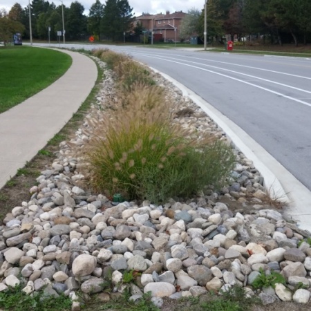
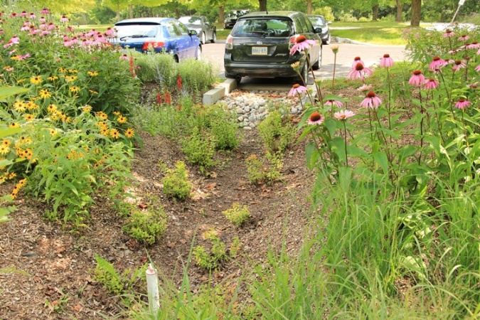
Swales are linear landscape features consisting of a drainage channel with gently sloping sides. Underground they may be filled with engineered soil and/or contain a water storage layer of coarse gravel material. Two variations on a basic swale are recommended as low impact development strategies, although using a combination design of both may increase the benefits:
Bioswales are sometimes referred to as 'dry swales', 'vegetated swales', 'water quality swales' or 'inline bioretention'. This type of structure is similar to a bioretention cell but with a long linear shape (surface area typically >2:1 )
Enhanced Grass Swales are a lower maintenance alternative, but generally have lower stormwater management potential. The enhancement over a basic grass swale is in the addition of check dams to slow surface water flow and create small temporary pools of water which can infiltrate the underlying soil.
Swales are an ideal technology for:
- Sites with long linear landscaped areas, such as parking lots
- Connecting with one or more other types of LID
| Property | Bioswale | Enhanced Grass Swale |
|---|---|---|
| Surface water | Minimal Any surface flow can be slowed with check dams | Ponding is encouraged with check dams |
| Engineered soil | Biomedia required | Amendment preferable when possible |
| Underdrain | Common | Uncommon |
| Maintenance | Medium to high | Low |
| Stormwater benefit | High | Medium |
| Biodiversity benefit | Increased with native planting | Lower |
The fundamental components of a swale are:
- Graded channel
- Planting
Additional components may include:
- Biomedia - an engineered soil mix
- Underdrain with clean out and inspection ports
- Impermeable membrane to prevent infiltration to soils below
- Check dams
<panelSuccess>
Bioswale?

</panelSuccess>
Planning Considerations[edit]
Planning Content
<panelSuccess>
Placeholder.

</panelSuccess>
Design[edit]
Pre-treatment and inlets
For more detail see article on Pre-treatment and inlets
To minimize erosion and maximize the functionality of the swale, sheet flow of surface water should be directed into the side of the BMP. Vegetated filter strips and shallow side slopes are ideal. Alternatively, a series of curb inlets can be employed, where each has some form of flow spreading incorporated. Single point inflow can cause increased erosion and sedimentation which will damage vegetation and contribute to BMP failure. Again, flow spreading devices can mitigate these processes, where concentrated point inflow is required.
Underdrains
- Underdrains should be constructed from perforated plastic (PVC or HDPE, between 100 - 200 mm). The larger 200 mm diameter is recommended to address any concerns about freezing conditions.
- The drain should be capped at the upstream end and discharge to an acceptable point downstream.
- The drain should be embedded into a coarse gravel layer, with a minimum of 100 mm aggregate below the pipe and 150 mm aggregate above. the pipe. To reduce the potential for sediment clogging the pipe, the gravel layer should be overlaid with a geotextile filter fabric.
- A vertical standpipe connected to the underdrain can be used as a cleanout and as a monitoring well.
Check dams
Check dams are a feature of enhanced swales. They promote infiltration and evaporation by promoting limited ponding. To design check dams into a swale:
- The height of each dam is determined by the depth of ponded water that will infiltrate in 24 hours. The infiltration may be into the native soils, into biomedia, or some other soil amendment may be proposed in the design.
- Dams are usually installed between 10-20 m along the swale. They are distributed such that the crest of each dam is at approximately the same elevation as the toe of the upstream dam. If the slope along the swale varies, so should the distance between the dams.
<panelSuccess>
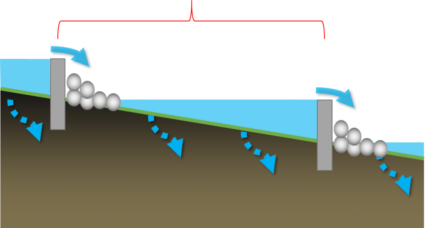
Distance between dams determined by equaling the crest of each dam, with the elevation of the toe of the upstream dam.

</panelSuccess>
Performance[edit]
Performance Content
<panelSuccess>
Placeholder
</panelSuccess>
Incentives and Credits[edit]
In Ontario
City of Mississauga
The City of Mississauga has a stormwater management credit program which includes RWH as one of their recommended site strategies[1].
LEED BD + C v. 4
SITES v.2
See Also[edit]
External Links[edit]
| SEND US YOUR QUESTIONS & FEEDBACK ABOUT THIS PAGE |