Difference between revisions of "Bioretention"
Jenny Hill (talk | contribs) |
Jenny Hill (talk | contribs) |
||
| Line 60: | Line 60: | ||
---- | ---- | ||
| − | === | + | ===Construction=== |
| − | + | {{:Bioretention: Construction}} | |
| − | |||
| − | |||
| − | + | ---- | |
| − | |||
| − | |||
| − | |||
| − | |||
| − | |||
| − | |||
| − | |||
| − | |||
| − | |||
| − | |||
===Incentives and Credits=== | ===Incentives and Credits=== | ||
<h4>In Ontario</h4> | <h4>In Ontario</h4> | ||
Revision as of 14:52, 11 July 2017
This article is about planted installations designed to capture and filter surface runoff through an engineered soil (biomedia) to underground infrastructure.
For simple systems (typically without regulatory control), see Rain gardens.
For linear systems, which convey flow, but are otherwise similar see Bioswales.
Overview[edit]
Bioretention cells are one of the most well recognized form of Low Impact Development. They can encompass all mechanisms of action: infiltration, filtration and evapotranspiration.
Bioretention cells are an ideal technology for:
- Fitting functional vegetation into urban landscapes
- Treating runoff collected from nearby impervious surfaces
The fundamental components of a bioretention cell are:
- Biomedia: An engineered soil mix
- Planting
- Storage layer of coarse aggregate
- Underdrain to redistribute or remove excess water
- Impermeable membrane to prevent infiltration to soils below
<panelSuccess>
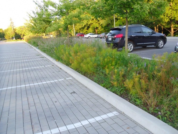
These bioretention cells at Edwards Gardens in Toronto receive inflow from hydraulically connected permeable paving.

</panelSuccess>
Planning considerations[edit]
Space
For optimal performance bioretention facilities should receive runoff from between 5 to 20 times their own surface area. In the conceptual design stage it is recommended to set aside approximately 10 - 20 % of a catchment area to the bioretention facility. Bioretention cell(s) work best when distributed so that no one facility receives runoff from more than 0.8 Ha. Although, there is a trade off to be considered regarding distributed collection and treatment against ease of maintenance.
Design for maintenance
Will the BMP be a snow storage facility in winter months? <h4blue>Infiltration</h4blue> Some form of stormwater landscaping (bioretention) can be fitted into most spaces. One of the key decisions is whether to infiltrate all of some of the collected water into the native soil. Although there are some constraints to infiltrating water, it is preferable to do so where possible. Partial infiltration facilities are a popular choice over 'tight' soils (infiltration ≤ 15 mm/hr).
| Type | Gravel layer | Underdrain | Liner | Mechanisms | Schematic |
|---|---|---|---|---|---|
| Rain gardens | - | - | - | These are the simplest construction, often used by residents or community groups. Volume reduction is through infiltration and evapotranspiration. | 
|
| Infiltrating bioretention | yes | - | - | This is a highly desirable type of bioretention where the soils permit infiltration at a great enough rate to empty the facility between storm events. Volume reduction is primarily through infiltration to the underlying soils, with some evapotranspiration. As there is no outflow from this BMP, it is particularly useful in areas where nutrient management is a concern to the watershed. | 
|
| Partially infiltrating bioretention | yes | yes | - | Including an underdrain in the gravel storage layer help to empty the facility between storm events, even over ‘tight soils’. The drain discharges to a downstream point, which could be an underground infiltration facility. Limited volume reduction is gained through infiltration and evapotranspiration. By raising the outlet of the discharge pipe the bottom portion of the BMP can only drain through infiltration. This creates a fluctuating anaerobic/aerobic environment which promotes denitrification. Increasing the period of storage has benefits for promoting infiltration, but also improves water quality for catchments impacted with nitrates. A complimentary technique is to use fresh wood mulch, which also fosters denitrifying biological processes. |  
|
| Biofilters (non-infiltrating) |
yes | yes | yes | This type may be required over contamination hot-spots or in very dense urban areas with a lot of other underground infrastructure. The design includes an impermeable base and sides, so that volume reduction is made only through evapotranspiration. This type of cell can be constructed above grade in any waterproof and structurally sound container, e.g. in cast concrete or a metal tank. | 
|
Design[edit]
Sizing
This article describes recommended design approaches when available space for the practice is constrained.
Before beginning the sizing calculations certain parameters must be known or estimated. See Bioretention: Sizing for parameter descriptions and conceptual diagram illustrating key components of bioretention practices. Note that some of these parameters are limited:
- The maximum total depth will be limited by construction practices i.e. not usually > 2 m.
- The maximum total depth may be limited by the conditions underground e.g. the groundwater or underlying geology/infrastructure.
- The minimum total depth will be limited by the need to support vegetation (e.g not less than 0.6 m to support deep rooting perennials and shrubs).
- Bioretention has a maximum recommended catchment impervious area to practice permeable (footprint) area ratio, R (or I/P ratio) of 20.
Size a bioretention cell receiving flows directly to the storage reservoir for a constrained depth[edit]
If there is a constraint to the depth (dT) of the practice, calculate the required storage reservoir footprint area (Ar), as:

Where:
- Ar = Area of the infiltration practice storage reservoir (m2)
- Ai = Catchment impervious area (m2)
- D = Duration of design storm (h)
- i = Intensity of design storm (mm/h)
- f' = design infiltration rate (m/h)
- n' = Effective porosity of the fill material in the storage reservoir of the practice
- dr = Storage reservoir depth, based on depth available between the elevation of the invert of the underdrain perforated pipe and one (1) metre above the seasonally high water table or top of bedrock (m) or other value determined to be suitable through groundwater mounding analysis.
If R is greater than 20, consider decreasing catchment impervious area (Ai) by draining less area to the practice.
Size a bioretention cell where drainage area and practice area are fixed[edit]
If the land area is limited, determine the I/P ratio, which is the ratio of catchment impervious area (Ai) to practice pervious footprint area (Ap):

Where:
- R = Ratio of catchment impervious area to practice pervious footprint area, also referred to as I/P ratio
- Ap = Practice pervious footprint area in m2
- Ai = Catchment impervious area in m2
Then calculate the required storage reservoir depth (dr), as:
![{\displaystyle d_{r}={\frac {D\left[(R\times i)-f'\right]}{n'}}}](https://wikimedia.org/api/rest_v1/media/math/render/svg/b5fa4822e3bd6865ab04dc8cd836641144d55c85)
Where:
- D = Duration of design storm (h)
- i = Intensity of design storm (m/h)
- f' = Design infiltration rate (m/h)
- n' = Effective porosity of the storage reservoir fill material
These equations assume that infiltration occurs primarily through the base of the facility.
This spreadsheet tool has been set up to perform all of the infiltration practice sizing calculations shown above.
Calculate drawdown time[edit]

In some situations, it may be possible to reduce the size of the bioretention required, by accounting for rapid drainage. Typically, this is only worth exploring over sandy soils with rapid infiltration. Note that narrow, linear bioretention features drain faster than round or blocky footprint geometries.
- Begin the drainage time calculation by dividing the storage reservoir area of the practice (Ar) by the perimeter (x).
- Use the following equation to estimate the time (t) to fully drain the facility:
![{\displaystyle t={\frac {nA_{r}}{f'x}}ln\left[{\frac {\left(d_{r}+{\frac {A_{r}}{x}}\right)}{\left({\frac {A_{r}}{x}}\right)}}\right]}](https://wikimedia.org/api/rest_v1/media/math/render/svg/5c7d5bdbfe7f03b02fd1451c74b7e9f784322498)
Where:
- n is the porosity of the storage reservoir fill material
- Ar is the storage reservoir footprint area (m2),
- f' is the design infiltration rate of the native soil (mm/h),
- x is the perimeter of the practice (m), and
- dr is the depth of the storage reservoir (m).
This 3 dimensional equation makes use of the hydraulic radius (Ar/x), where x is the perimeter (m) of the facility.
Maximizing the perimeter of the facility directs designers towards longer, linear shapes such as bioswales.
<panelSuccess>
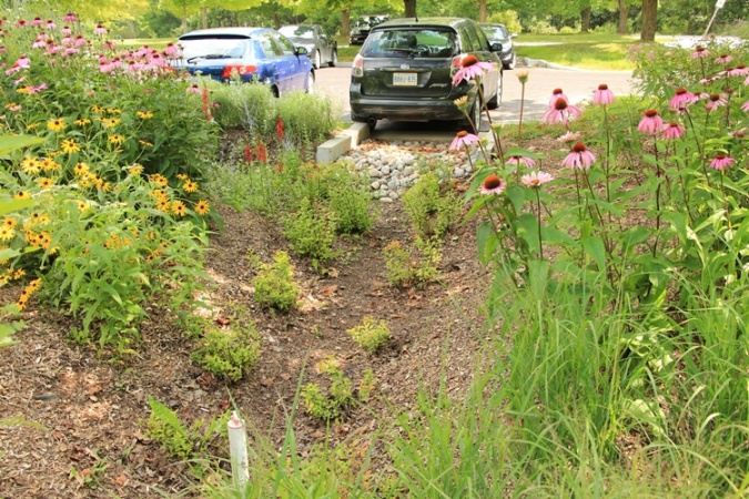
Bioretention cell capturing and treating runoff from adjacent parking lot at the Kortright Centre, Vaughan.

</panelSuccess>
Construction[edit]
Incentives and Credits[edit]
In Ontario
City of Mississauga
The City of Mississauga has a stormwater management credit program which includes RWH as one of their recommended site strategies[1].
LEED BD + C v. 4
Sustainable sites: Rainwater management (up to 3 points)
- Two points (or 1 point for Healthcare) will be awarded if the project manages "the runoff from the developed site for the 95th percentile of regional or local rainfall events."
- Three points (or 2 points for Healthcare) will be awarded if the project manages "the runoff from the developed site for the 98th percentile of regional or local rainfall events."
OR
- For zero-lot-line projects only, 3 points (or 2 points for Healthcare) will be awarded if the project manages "the runoff from the developed site for the 85th percentile of regional or local rainfall events."
SITES v.2
See Also[edit]
External Links[edit]
| SEND US YOUR QUESTIONS & FEEDBACK ABOUT THIS PAGE |