Difference between revisions of "Pipes"
Jump to navigation
Jump to search
Jenny Hill (talk | contribs) |
Jenny Hill (talk | contribs) |
||
| Line 12: | Line 12: | ||
</div> | </div> | ||
<div class="col-md-4"> | <div class="col-md-4"> | ||
| + | <panelSuccess> | ||
<gallery mode="packed" widths=300px heights=300px> | <gallery mode="packed" widths=300px heights=300px> | ||
Perforated Pipe 550x550.jpg| Pipe | Perforated Pipe 550x550.jpg| Pipe | ||
</gallery> | </gallery> | ||
| + | </panelSuccess> | ||
</div> | </div> | ||
<div class="col-md-12"> | <div class="col-md-12"> | ||
[[Category:Materials]] | [[Category:Materials]] | ||
Revision as of 20:04, 11 July 2017
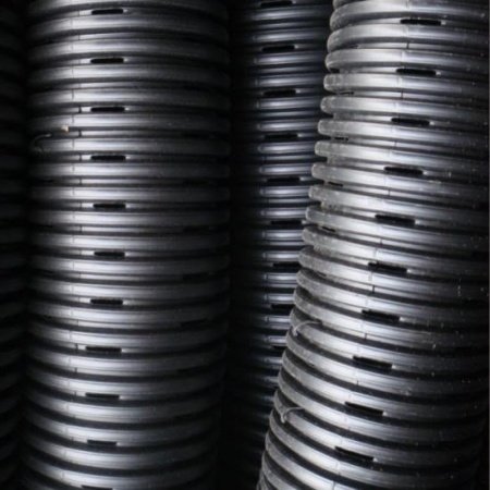
- Perforated pipes should be continuously perforated, smooth interior HDPE (or equivalent material) with a minimum inside diameter of 100 mm.
- Where freezing is a concern, horizontal underdrain pipes should be over-sized to a minimum 200 mm diameter.
- Perforations should be 10 mm in diameter and distributed at least every 90 deg around the pipe.
- All underdrains should be capped on the upstream end.
- At least one vertical well per BMP is recommended, for inspection and monitoring water level.
- Well(s), of 100 - 150 mm diameter perforated pipe, should extend to the bottom of the facility.
- Where a horizontal underdrain is being installed, an upstream and a downstream well should be coupled to the underdrain pipe. The pair of wells can then be used to flush out the length of underdrain if required.
- The exposed tops of all wells should be fitted with lockable caps.
- Non-perforated pipes should be used for conveyance to and away from the facility, including overflow.
- To function correctly, the capacity of the overflow pipes must be greater than the inlet(s).
