Difference between revisions of "Wells"
| (6 intermediate revisions by the same user not shown) | |||
| Line 1: | Line 1: | ||
<imagemap> | <imagemap> | ||
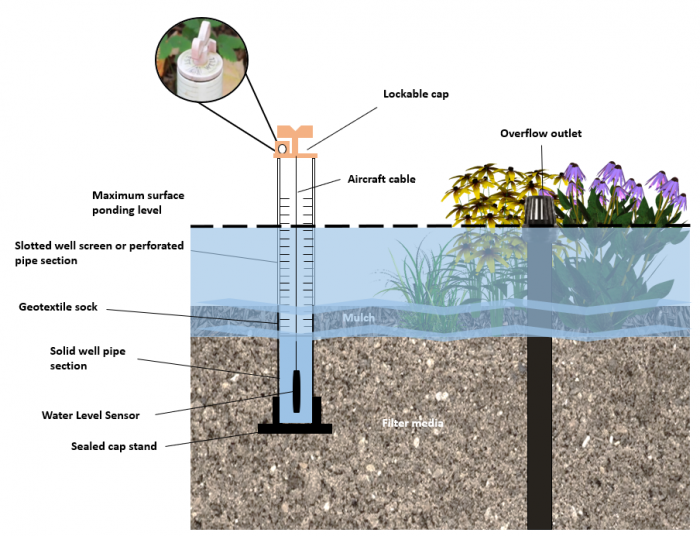
| − | File:Shallow monitoring well.png |thumb| | + | File:Shallow monitoring well update.png|thumb|700px|Cross-section view of a bioretention cell with a shallow monitoring well. For further details click here for [https://sustainabletechnologies.ca/app/uploads/2016/08/LID-IM-Guide-2016-1.pdf STEP's, Low Impact Development Stormwater Management Practice Inspection and Maintenance Guide (Pg. 195 - 204).] <span style="color:red">''A note: The following is an "image map", feel free to explore the image with your cursor and click on highlighted labels that appear to take you to corresponding pages on the Wiki.''</span> |
| − | |||
| − | |||
| − | |||
| − | |||
| − | |||
| − | |||
| − | |||
| − | |||
| − | |||
| − | |||
| − | |||
| − | |||
| − | |||
| − | |||
| − | |||
| − | |||
| − | |||
| − | |||
| + | rect 16 383 135 411 [[Geotextiles|Geotextile Sock]] | ||
| + | rect 207 30 318 134 [[Wells|Lockable Cap]] | ||
| + | rect 351 162 409 207 [[Wells|Lockable Cap]] | ||
| + | rect 494 111 583 134 [[Wells|Lockable Cap]] | ||
| + | rect 43 521 183 550 [[Digital technologies|Water Level Sensor]] | ||
| + | rect 373 481 396 536 [[Digital technologies|Water Level Sensor]] | ||
| + | rect 361 455 405 545 [[Wells|Solid Well Pipe]] | ||
| + | rect 56 435 164 483 [[Wells|Well Casing]] | ||
| + | rect 112 238 240 285 [[Flow through media|Surface Ponding]] | ||
| + | rect 641 161 758 181 [[Overflow|Overflow]] | ||
| + | rect 677 252 716 684 [[Pipes|Overflow Outlet Pipe]] | ||
| + | rect 246 395 889 435 [[Mulch|Mulch]] | ||
| + | rect 245 436 889 681 [[Filter Media|Filter Media]] | ||
| + | rect 479 307 580 409 [[Grasses]] | ||
| + | rect 245 294 889 394 [[Flow through media|Surface Ponding]] | ||
| + | rect 579 216 880 396 [[Plant Lists|Vegetation]] | ||
</imagemap> | </imagemap> | ||
| − | {{TOClimit| | + | {{TOClimit|3}} |
This article gives tips on the design and installation of monitoring wells into LID practices. It does not address the much deeper wells used to monitor groundwater levels. | This article gives tips on the design and installation of monitoring wells into LID practices. It does not address the much deeper wells used to monitor groundwater levels. | ||
| Line 37: | Line 35: | ||
* Locate the well in the deepest portion of the surface ponding area or where ponding most frequently occurs. | * Locate the well in the deepest portion of the surface ponding area or where ponding most frequently occurs. | ||
* Measure the depth of the water level sensor in the well, relative to the filter media surface to translate sensor readings into surface ponding depth measurements. | * Measure the depth of the water level sensor in the well, relative to the filter media surface to translate sensor readings into surface ponding depth measurements. | ||
| − | * Ensure there is a solid cap on the bottom of the well to provide a small water reservoir (e.g., 100 mm deep) to keep the water level sensor submerged during dry conditions. This practice also helps with checking calibration of the sensor. | + | * Ensure there is a solid cap on the bottom of the well to provide a small water reservoir (e.g., 100 mm deep) to keep the water level sensor submerged during dry <br> conditions. This practice also helps with checking calibration of the sensor. |
==Deep wells== | ==Deep wells== | ||
| − | Many types of LID practices are designed to retain water within an internal water storage reservoir or layer (e.g. full and partial infiltration [[Bioretention|bioretention], [[Stormwater tree trench|stormwater tree trench]] and [permeable pavements|permeable pavement]] designs, infiltration trenches and chambers, and exfiltration trenches). To facilitate measurement of water level in the internal water storage reservoir or layer and periodically evaluate drainage performance over the operating life cycle of the facility, include a monitoring well located in the lowest elevation portion of the practice or system: | + | <imagemap> |
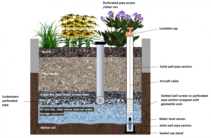
| + | File:Deep monitoring well update.png|thumb|700px|Cross-section view of a partial infiltration bioretention cell with a deep monitoring well. For further details click here for [https://sustainabletechnologies.ca/app/uploads/2016/08/LID-IM-Guide-2016-1.pdf STEP's, Low Impact Development Stormwater Management Practice Inspection and Maintenance Guide (Pg. 195 - 204).] <span style="color:red">''A note: The following is an "image map", feel free to explore the image with your cursor and click on highlighted labels that appear to take you to corresponding pages on the Wiki.''</span> | ||
| + | |||
| + | rect 543 234 586 541 [[Pipes|Clean out / Access Pipe]] | ||
| + | rect 573 8 756 50 [[Pipes|Clean out / Access Pipe]] | ||
| + | rect 719 656 739 725 [[Digital technologies|Water Level Sensor]] | ||
| + | rect 708 552 715 686 [[Geotextiles|Geotextile Sock]] | ||
| + | rect 742 551 749 690 [[Geotextiles|Geotextile Sock]] | ||
| + | rect 705 147 754 204 [[Wells|Locked Well Cap]] | ||
| + | rect 890 145 1002 169 [[Wells|Locked Well Cap]] | ||
| + | rect 706 201 748 509 [[Wells|Solid Well Pipe]] | ||
| + | rect 712 554 744 687 [[Wells|Perforated Well Pipe]] | ||
| + | rect 335 61 800 235 [[Plant Lists|Vegetation]] | ||
| + | rect 219 110 337 260 [[Plant Lists|Vegetation]] | ||
| + | rect 541 538 590 585 [[Underdrains|Underdrain]] | ||
| + | rect 219 318 792 513 [[Filter Media|Filter Media]] | ||
| + | rect 218 510 791 551 [[Choker layer|Choker Layer (HPB)]] | ||
| + | rect 218 554 794 689 [[Clear Stone / Internal Water Storage (IWSZ)|Bioretention: Internal water storage]] | ||
| + | rect 222 260 794 317 [[Mulch|Mulch]] | ||
| + | rect 171 682 698 749 [[Soil groups|Native Soil]] | ||
| + | rect 792 405 844 749 [[Soil groups|Native Soil]] | ||
| + | rect 173 405 217 684 [[Soil groups|Native Soil]] | ||
| + | </imagemap> | ||
| + | |||
| + | <br>Many types of LID practices are designed to retain water within an internal water storage reservoir or layer (e.g. full and partial infiltration [[Bioretention|bioretention]], [[Stormwater tree trench|stormwater tree trench]] and [[permeable pavements|permeable pavement]] designs, infiltration trenches and chambers, and exfiltration trenches). To facilitate measurement of water level in the internal water storage reservoir or layer and periodically evaluate drainage performance over the operating life cycle of the facility, include a monitoring well located in the lowest elevation portion of the practice or system: | ||
* Include monitoring wells in design drawings and details and install at an appropriate time during construction, or as part of repair work for facilities in need of rehabilitation. | * Include monitoring wells in design drawings and details and install at an appropriate time during construction, or as part of repair work for facilities in need of rehabilitation. | ||
* Ensure the perforated section of the well is located within the internal water storage reservoir or layer only, and that it extends to the bottom elevation of the practice at a minimum. | * Ensure the perforated section of the well is located within the internal water storage reservoir or layer only, and that it extends to the bottom elevation of the practice at a minimum. | ||
| Line 46: | Line 68: | ||
* A standard monitoring well casing and cap or monument to protect, secure and provide access to the well should also be included. | * A standard monitoring well casing and cap or monument to protect, secure and provide access to the well should also be included. | ||
* Ensure there is a solid cap on the bottom of the well to provide a small water reservoir (e.g., 100 mm deep) to keep the water level sensor submerged during dry conditions. This practice also helps with checking calibration of the sensor. | * Ensure there is a solid cap on the bottom of the well to provide a small water reservoir (e.g., 100 mm deep) to keep the water level sensor submerged during dry conditions. This practice also helps with checking calibration of the sensor. | ||
| − | * Where possible, wells should be located in areas with little or no vehicular traffic for ease of access. | + | * Where possible, wells should be located in areas with little or no vehicular traffic for ease of access. <br> |
| − | + | </br> | |
| − | |||
| − | |||
| − | < | ||
| − | |||
| − | |||
| − | |||
| − | |||
| − | |||
| − | |||
| − | |||
| − | |||
| − | |||
| − | |||
| − | |||
| − | |||
| − | |||
| − | |||
| − | |||
| − | |||
| − | |||
| − | |||
| − | |||
| − | |||
| − | |||
| − | |||
| − | |||
| − | |||
| + | ==Monitoring Well Specifications== | ||
{| class="wikitable" | {| class="wikitable" | ||
|- | |- | ||
| Line 96: | Line 92: | ||
==External Links== | ==External Links== | ||
| − | [https://www.toronto.ca/wp-content/uploads/2021/08/8f13-ecs-specs-gi-dwgs-T-850.041-Rev0-Sep2021.pdf Monitoring Well Standard Drawings from City of Toronto’s Green infrastructure in the Right-Of-Way] | + | '''[https://www.toronto.ca/wp-content/uploads/2021/08/8f13-ecs-specs-gi-dwgs-T-850.041-Rev0-Sep2021.pdf Monitoring Well Standard Drawings from City of Toronto’s Green infrastructure in the Right-Of-Way]''' |
| − | + | *Review the above technical drawings of well types used by the City of Toronto in unpaved areas, and in paved areas with both options of geotextile lined membrane and an unlined typical with a PVC slotted well. | |
| − | |||
| − | |||
| − | {{#widget:YouTube|id=P1JbuPlT7m4}} | + | *Review the below posted video showing how to install shallow and deep monitoring wells <br> |
| + | :and how to effectively monitor the LID BMP practices they are used in conjunction with. <br> | ||
| + | </br> | ||
| + | {{#widget:YouTube|500px|id=P1JbuPlT7m4}} | ||
Latest revision as of 18:08, 3 November 2022
This article gives tips on the design and installation of monitoring wells into LID practices. It does not address the much deeper wells used to monitor groundwater levels. Monitoring wells are frequently installed on infiltrating systems such as bioretention, bioswales, infiltration trenches and hybrids thereof. The two questions most frequently addressed are:
- How quickly is surface ponding being infiltrated beneath the surface?
- How quickly is the facility draining through exfiltration to native soils and/or through an underdrain?
Shallow wells[edit]
For bioretention cells, stormwater tree trenches and enhanced swales featuring surface ponding areas, to measure the depth of ponding on the surface of the practice, and rate at which the ponded water drains, install a shallow well with a water level logger:
- Use a section of perforated pipe or well screen with a geotextile sock that will allow ponded water to enter the well while preventing sediment from accumulating within it.
- Locate the well in the deepest portion of the surface ponding area or where ponding most frequently occurs.
- Measure the depth of the water level sensor in the well, relative to the filter media surface to translate sensor readings into surface ponding depth measurements.
- Ensure there is a solid cap on the bottom of the well to provide a small water reservoir (e.g., 100 mm deep) to keep the water level sensor submerged during dry
conditions. This practice also helps with checking calibration of the sensor.
Deep wells[edit]
Many types of LID practices are designed to retain water within an internal water storage reservoir or layer (e.g. full and partial infiltration bioretention, stormwater tree trench and permeable pavement designs, infiltration trenches and chambers, and exfiltration trenches). To facilitate measurement of water level in the internal water storage reservoir or layer and periodically evaluate drainage performance over the operating life cycle of the facility, include a monitoring well located in the lowest elevation portion of the practice or system:
- Include monitoring wells in design drawings and details and install at an appropriate time during construction, or as part of repair work for facilities in need of rehabilitation.
- Ensure the perforated section of the well is located within the internal water storage reservoir or layer only, and that it extends to the bottom elevation of the practice at a minimum.
- Design and install the well so that surface water will not affect water level readings.
- A standard monitoring well casing and cap or monument to protect, secure and provide access to the well should also be included.
- Ensure there is a solid cap on the bottom of the well to provide a small water reservoir (e.g., 100 mm deep) to keep the water level sensor submerged during dry conditions. This practice also helps with checking calibration of the sensor.
- Where possible, wells should be located in areas with little or no vehicular traffic for ease of access.
Monitoring Well Specifications[edit]
| Feature | Notes |
|---|---|
| Pipe | Should consist of 100 to 150 mm diameter solid and perforated pipe sections joined together by threading or straight couplings. Perforated pipe section should consist of well screen pipe or smooth interior walled, rigid HDPE or PVC pipe with slot perforations along the full length. |
| Geotextile sock | The perforated or well screen section of the well pipe should be wrapped with a geotextile filter fabric sock to prevent sediment from accumulating in the well over time. |
| Bottom cap | The bottom of the well should be sealed with a cap to provide a small (e.g., 100 mm deep) reservoir of water to keep the water level sensor wet during dry weather. |
| Length | Shallow wells should extend into the filter media by a minimum of 150 mm. Deep wells should extend into the native soil below the facility by a minimum 150 mm. If the underdrain perforated pipe is installed in a shallow trench below the bottom of the facility, the well should extend 150 mm below the invert of the perforated pipe. Top elevation should be above the surface overflow outlet elevation or maximum ponding depth to prevent surface water from entering the well. |
| Top cap or monument | The well top should be finished with a lockable cap or standard monitoring well casing and monument to protect, secure and provide access to it. |
| Well casing | For deep wells, the well casing should be sealed at the surface to prevent surface water from flowing along the sides of the well and affecting internal storage reservoir water level readings. Bentonite clay is often used for this purpose. |
External Links[edit]
Monitoring Well Standard Drawings from City of Toronto’s Green infrastructure in the Right-Of-Way
- Review the above technical drawings of well types used by the City of Toronto in unpaved areas, and in paved areas with both options of geotextile lined membrane and an unlined typical with a PVC slotted well.
- Review the below posted video showing how to install shallow and deep monitoring wells
- and how to effectively monitor the LID BMP practices they are used in conjunction with.