User talk:DanielFilippi
Overview[edit]
Stormwater tree trenches are linear tree planting structures that feature supported impermeable or permeable pavements that promote healthy tree growth while also helping to manage runoff. They are often located behind the curb within the road right-of-way and consist of subsurface trenches filled with modular structures and growing medium, or structurally engineered soil medium, supporting an overlying sidewalk pavement. They improve tree health by providing access to soil, air and stormwater for irrigation, allowing them to survive longer in harsh urban conditions.
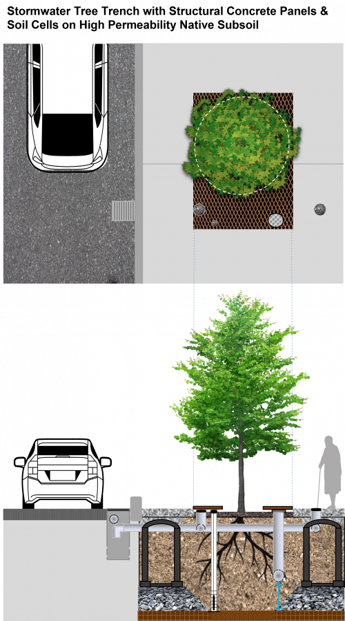
They also provide road and walkway drainage, contribute to stormwater pollutant removal and decrease the volume of urban runoff entering local waterways. They feature trees, soil, stormwater inlet and outlet structures, distribution and drainage pipes, and may include soil support structures, structural soil medium or structural concrete panels (as seen in the image map to the right). The tree planting pits and adjacent supported sidewalk pavements provide more soil volume for tree growth and water retention.
Take a look at the downloadable Stormwater Tree Trenches Fact Sheet below for a .pdf overview of this LID Best Management Practice:

Stormwater tree trench installations include:
- Overlying impermeable or permeable pavements
- Trees (tolerant to northern. urban conditions)
- Planting soil
- Modular soil support or "soil cell" structures (optional)
- Structural soil (optional)
- Structural concrete panels (optional)
- Stormwater inlet and outlet structures
- Distribution and drainage pipes
- Choker layer (optional)
- Geogrid and geotextile (optional)
- Aggregate base
Stomwater tree trenches are ideal for:
- Sites with limited space for other surface stormwater BMPs that also possess primarily impermeable coverage (i.e. a municipality's "right-of-way", which includes the edge between private/public property, roadways, sidewalks and utility service land use)
- Areas with limited greenspace
- Projects with high traffic loads (pedestrian and vehicular), laneways, pedestrian plazas and walkways
Additional components may include:
- Internal water storage layer
- Distribution and underdrain pipe access and clean-out features
- Monitoring well screened within internal water storage layer
- Root barriers in locations where tree rooting is not desired
Planning considerations[edit]
A commonly held view is that a tree's root system will be similar to it's visible crown. For many trees, this is not the case, as roots will more often spread much more widely, but to a shallower depth [1]. For more detailed information on planning (site) considerations see Bioretention.
Site Topography[edit]
Contributing slopes should be between 1-5%. The bottom of the trench and distribution pipes should be graded flat to allow water to spread out.
Planting in slopes[edit]
Smooth slopes should be amended into localized terraces by the Landscape Architect when planting large trees into slopes > 5 %. [2]. Contributing slopes should be between 1-5%. The bottom of the trench and distribution pipes should be graded flat to allow water to spread out.
Wellhead Protection[edit]
Facilities receiving road or parking lot runoff should not be located within 2 year time-of-travel wellhead protection areas.
Water Table[edit]
Maintaining a separation of 1 m between the elevations of the bottom of the trench and the seasonally high water table, or top of bedrock, is recommended. Lesser or greater values may be considered based on groundwater mounding analysis. See STEP LID Planning and Design Guide for further guidance and spreadsheet tool.
Soil[edit]
Tree trenches can be constructed over any soil type, but hydrologic soil group A and B are best for achieving water balance objectives. Facilities designed to infiltrate water should be located on portions of the site with the highest infiltration rates. Native soil infiltration rate at the proposed location and depth should be confirmed through in-situ measurements of hydraulic conductivity under field saturated conditions.
Drainage Area[edit]
Typical contributing drainage areas are between 150-300 m2 per tree, with a maximum of 450 m2 per tree.
Setback from Buildings[edit]
Tree trenches should be set back from the building far enough to allow for the tree canopy to grow to a healthy, mature size, depending on the species selected. A minimum setback of 4 m from buildings is recommended.
Overhead Wires[edit]
Tree trenches should be implemented with caution under overhead wires. If overhead wires conflict with proposed tree trench locations, check the height of existing wires, and choose small form trees that will not grow tall enough to interfere with wires.
Pollution Hot Spot Runoff[edit]
Tree trenches receiving road or parking lot runoff are not recommended in these areas.
Proximity to Underground Utilities[edit]
Designers should consult local utility design guidance for the horizontal and vertical clearances required.
Karst[edit]
Tree trenches designed to drain primarily by infiltration are unsuitable in areas of known or implied karst topography.
Design[edit]
Geometry and Site Layout[edit]
Tree trenches are often modular systems connected hydrologically through sub-surface stormwater distribution and drainage pipes. Road runoff may be directed to the trench via curb cuts or depressed drains located at tree openings.
Inlets[edit]
Water can enter the tree trench in a variety of ways: from the overlying sidewalk via sheet flow or curb cuts into tree openings, trench drains or infiltration through permeable pavement; and from the road via distribution pipes connected to road or side inlet catch basins and curb cuts or depressed drains at tree openings. It is recommended that each tree trench have multiple inlets to keep the contributing drainage area relatively small, which provides redundancy to the system. Inlet structures and distribution pipes should be offset from tree root ball locations to avoid impact of de-icing salt laden runoff on newly planted trees during establishment.
Pre-Treatment[edit]
If water enters the trench via a catch basin, a removable pre-treatment device, like a Goss trap or proprietary catch basin insert device or filter should be included to help retain coarse sediment, debris and floatables and prevent it from entering the pipe or trench. Inlet structures should have a sump and curb cut inlets should include stone diaphragms or stone mulch to dissipate energy and spread flows. Pre-treatment features should be easy to access and clean.

Soil Volume[edit]
Each tree planted should have access to a minimum 30 m3 of soil volume, including the growing medium within the tree pit and growing or structural soil medium below adjacent supported pavement. If more than one tree shares the same trench a minimum 20 m3 of soil per tree may be acceptable.
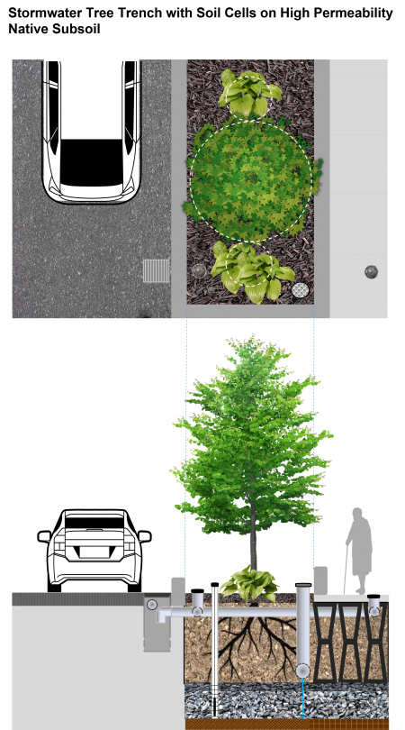
Modular Soil Support Systems[edit]
Modular soil support systems (also referred to as “soil cells”) consist of plastic or concrete structures, available in a variety of shapes and sizes, that provide structural support for the overlying pavement while providing uncompacted planting soil within the tree root zone. They are installed adjacent to tree pits to provide room for roots to spread out under the supported pavement portion of the trench. Growing medium backfill typically has higher organic matter content than structural soil medium. The looser structure and higher nutrient content of the growing medium provides the most favorable environment for healthy tree growth in an urban setting.
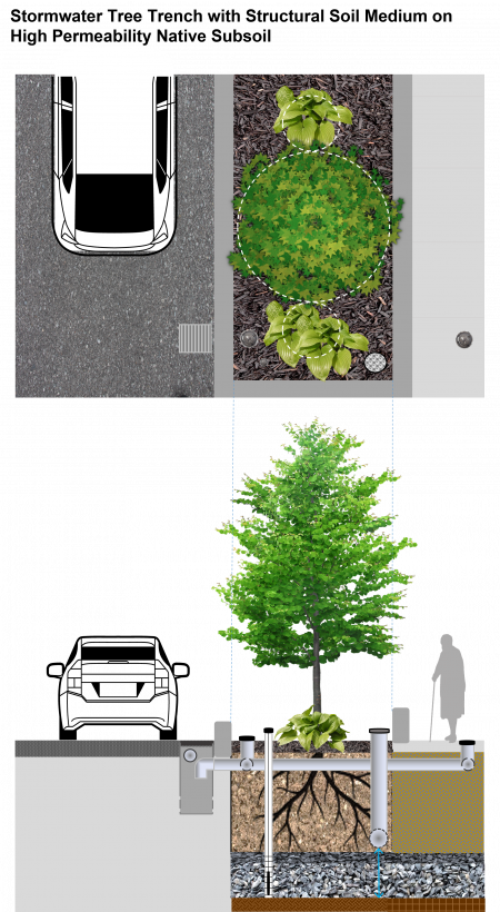
Structural Soil Medium[edit]
Structural soil is an engineered soil medium that can be compacted to support sidewalk or roadway pavement installation requirements while also permitting tree root growth. Structural soil medium filled trenches are installed adjacent to tree pits to provide room for tree roots to spread out under the supported pavement portion of the tree trench.
Structural Concrete Panels[edit]
Trenches where the overlying pavement consists of structural concrete panels supported on each side by concrete footings and rows of modular soil support structures installed on aggregate bases is another configuration. The benefit of this approach is that the native subgrade soil under the portions of the trench below tree pits and between rows of supports does not need to be highly compacted, allowing greater opportunity for drainage via infiltration (see image map within the 'Overview' section of this page).
Conveyance and Overflow[edit]
Runoff is directed from overlying and adjacent pavements to the trench through such means as tree openings, perforated distribution pipes connected to catchbasins or trench drains, or curb cuts and depressed drains to tree openings. Runoff water percolates through the growing or structural soil medium to the underlying native subgrade soil. When runoff volume exceeds the trench water storage capacity, the perforated underdrain pipe directs excess filtered water to a downstream outlet storm sewer or other practice. During intense storm events, runoff in excess of the infiltration capacity of the growing or structural soil medium will overflow to the storm sewer either through an outlet pipe connection in the catch basin or via surface overflow standpipes or structures within tree openings.
Configuration[edit]
Structural concrete panel and modular soil support system trench configurations should provide a better growing environment for trees, and thereby improve tree longevity. Structural soil medium and structural concrete panel trench configurations provide the benefits of being more adaptable to being fit around utilities or existing trees and provide easier access to utilities when repairs are needed.
Distribution and Underdrain pipes[edit]
To maximize the quantity of growing or structural soil medium irrigated, distribution pipes should be installed flat, just below modular soil support tops or at the top of the structural soil media layer and in both tree pit and supported pavement portions of the trench. Pipe perforations should be oriented to the sides and section ends should be sealed with a solid cap. To enhance runoff volume reduction underdrain pipes can be installed above the bottom of the trench and/or include flow control. Alternatively, the underdrain pipe may be installed on trench bottom and connected to a riser assembly in the outlet manhole. It is critical to include connections to outlet storm sewer pipes and multiple cleanout access points.
Variations of Stormwater Tree Trenches[edit]
Below, find three alternate stormwater tree trench configurations, that differ based off of native subgrade soil permeability and associated infiltration rates, structural support systems used (modular soil cell systems vs. structural soil medium) and placement of the underdrain for the system based off of these factors. All the images below are partial image map drawings, which only feature interactive differing specifications with highlighted labels that appear to take you to corresponding pages on the Wiki tare not found in the image map at the top of the page, highlighting features of a Stormwater tree trench with structural concrete panels and soil cells.

| Material | Specification |
|---|---|
| Growing Medium |
|
| Modular Soil Support System |
|
| Structural Soil Medium |
|
| Structural Concrete Panel |
|
| Aggregate Base |
|
| Geotextile & Geogrid |
|
| Underdrain |
|
| Stormwater Distribution Pipe |
|
General Specifications[edit]
Growing Medium[edit]
- Should be Canadian Soil Classification System sandy loam with combined silt- and clay-sized content between 18-35%; and sand- to fine gravel-sized content (0.074 to 5 mm dia.) between 65-82%.
- Should have a pH value between 6.0 and 8.0.
- Percent organic matter shall be 3-5%, by dry weight.
- Soluble salt level shall be less than 2 mmhos/cm.
- Growing medium should be compacted to 80-90% below the tree root ball to prevent settling.
- Bioretention filter media (see Bioretention Fact Sheet) may be suitable for use as growing medium, depending on climate and tree species.
Modular Soil Support System[edit]
- Structures are designed to be filled with growing medium for tree rooting and support a vehicle loaded pavement up to and including AASHTO H-20 and Ontario Building Code standards for sidewalks.
- Critical to modular soil support system design is that each structure or layer of structures shall be structurally independent of all adjacent structures, such that one or multiple layers can be removed after the completion of the installation to facilitate future utility installation or repair.
Structural Soil Medium[edit]
- Structural soils are installed in the trench adjacent to tree planting pits under permeable or impermeable pavements.
- Structural soils consist of 3 components, mixed in the following proportions by weight: crushed stone (79.07%), clay loam soil (20%), and hydrogel tackifier (0.03%).
- Crushed stone (granite or limestone) should be narrowly graded from 20 to 40 mm diameter, highly angular with no fines.
- The clay loam soil should conform to the Canadian soil classification system (gravel <5%, sand 25-30%, silt 20-40%, clay 25-40%). Organic matter should range between 2 to5% by dry weight.
- The hydrogel, a potassium propenoate-propenamide copolymer, is added in a small amount to act as a tackifier, preventing separation of the stone and soil during mixing and installation.
- Total moisture at mixing should be 10% as per AASHTO T-99 optimum moisture.
- Mixing can be done on a paved surface using front end loaders. Typically the stone is spread in a layer, the dry hydrogel is spread evenly on top and the screened moist clay loam soil is the top layer.
- The entire pile is turned and mixed until a uniform blend is produced. The structural soil is then installed and compacted in 150 mm lifts.
Structural Concrete Panel[edit]
- Structural concrete panel is 250 mm thick, contains rebar reinforcements and sits on equal-sized concrete footing supports on rows of modular soil support structures, which are supported by a minimum 150 mm base of compacted granular material.
- Decompact native subgrade soil under tree openings and between granular bases of modular soil support structure rows during installation for better infiltration drainage performance.
Aggregate Base[edit]
- Aggregates are used in modular soil support systems below the structures as the trench base layer, and in some cases, on top of the structures, as the pavement base layer.
- Specifications for aggregate base materials and depths shall be determined by the designing Engineer based on structural loading and hydraulic requirements.
Geotextile and Geogrid[edit]
- Geotextile, geogrid or combinations are typically used on top of modular soil support structures and along the sides of the trench to separate growing or structural soil mediums from native soil or aggregate backfill.
Geotextile and geogrid should not be installed on sides adjacent to pervious landscaped areas to provide opportunities for tree roots to grow outside the trench in these locations.
- Geotextile, geogrid or combination products in contact with modular soil support system structures should be according to manufacturer’s specifications.
- Geotextile material specifications should conform to Ontario Provincial Standard Specification (OPSS) 1860 for Class II geotextile fabrics.
- Geotextile installed on tree trench sides and around perforated distribution and underdrain pipes should be woven monofilament or non-woven needle punched fabrics. Woven slit film and non-woven heat bonded fabrics should not be used as they are prone to clogging.
- Where a root barrier is needed to prevent the migration of roots out of the tree trench, use impermeable ribbed barrier material with a thickness of 1-2 mm.
Underdrain Pipe[edit]
- Should be minimum 150 mm dia. perforated HDPE or equivalent material, smooth interior wall and continuously perforated with geotextile sock.
- A standpipe from the underdrain pipe to the growing medium or pavement surface can be used for inspection and maintenance. The top of the standpipe should be covered with a sealable cap and secured with a vandal-proof fastener.
Stormwater Distribution Pipe[edit]
- Solid pipe from inlet structures should transition to perforated pipe once 300 mm inside the trench.
- Perforated pipe should be minimum 150 mm dia. rigid, smooth interior wall HDPE or PVC with perforations on sides, wrapped with geotextile sock, with capacity and perforation specifications confirmed by the designing Engineer based on hydraulic requirements.
Inspection and Maintenance[edit]
Tree trenches have fewer maintenance requirements than bioretention cells or bioswales, but maintenance is still critical to their success. The most critical maintenance task is the removal of trash, sediment and debris accumulated in inlet structure sumps, gravel diaphragms and tree openings at curb cuts. This should be done at least once per year, however the frequency will depend on pavement uses, traffic volumes and tree canopy size. Inspect new trenches closely during the first two years of operation to measure the rate of accumulation and set an optimal maintenance frequency.
Underdrains and distribution pipes within the tree trench must be designed for ease of maintenance. Pipe couplings should be no greater than 45 degrees to allow inspection and cleaning equipment to access it, with enough cleanout access standpipes or structures to access the full length of the pipe.
Tree care is also an important part of tree trench maintenance. Provide regular irrigation and weed control in the tree openings until newly planted trees are fully established. Prune trees as needed once established to prevent safety hazards to pedestrians, overhead utility lines, and adjacent buildings. Monitor trees for damage by insects and other pests and replace trees that are in decline. A tree trench containing a diseased or dying tree is not a fully functional practice.
See further details here: Stormwater Tree Trenches: Maintenance
| Latin Name | Common Name |
|---|---|
| Ulmus americana | American Elm |
| Acer x freemanii | Freeman’s Maple |
| Alnus incana | White Alder |
| Celtis occidentalis | Hackberry |
| Gleditsia triacanthos var. inermis | Thornless Honeylocust |
| Gymnocladus dioicus | Kentucky Coffeetree |
| Quercus bicolor | White Oak |
| Quercus macrocarpa | Burr Oak |
| Quercus rubra | Red Oak |
Benefits of Trees[edit]
Stormwater Tree Trenches help support healthy street trees in urban settings where conventional plantings have limited space for root establishment. Trees play a critical role in stormwater management from reducing runoff through canopy interception, evapotranspiration, filtering out pollutants, and increasing infiltration capacity of soils, to retaining runoff. Trees also provide a myriad other environmental benefits, from shading impervious surfaces and thereby reducing urban heat island effects, to providing wildlife habitat and improving the aesthetics of streets and neighbourhoods. Research has shown that healthy trees increase property values, retail spending and contribute to a sense of community pride and safety.
At right is a list of trees that are known to tolerate conditions in northern (Zone 3) urban stormwater tree trenches.
Species selection[edit]
For a detailed overview with in-depth information on species selection please visit our Plant lists wiki page and you can continue on to our further detailed tables showcasing how to develop planting plans that include selection of species for specific functions in several stormwater tree trenches and other LID practices.
Soil cells[edit]
These are (usually plastic) supporting structures placed around the trees and beneath adjacent paved areas. They prevent compaction to the roots of the tree and prevent root damage to the paving. They are sometimes configured to receive stormwater and to enclose ponded water which can then infiltrate the soil surrounding the tree. Things to consider in design:
- If the system is unlined it is hydraulically equivalent to a bioretention cell and provides similar water quality benefits.
- If the system is lined and underdrained it is hydraulically similar to a large stormwater planter. Depending on the design detail it may retain significant stormwater within the planting soil volume and will provide water quality benefits.
- Structures are designed to be filled with growing medium for tree rooting and support a vehicle loaded pavement up to and including AASHTO H-20 and Ontario Building Code standards for sidewalks.
- Critical to modular soil support system design is that each structure or layer of structures be independent of all adjacent ones, such that one or multiple layers can be removed to facilitate future utility installation or repair.

Underdrain[edit]
Performance[edit]
| BMP | Water Balance | Water Quality | Erosion Control |
|---|---|---|---|
| Tree Trench | Partial-based on on native soil infiltration rate and if flow restrictor is used | Yes-size for water quality storage requirement | Partial-based on native soil infiltration rate, available storage and if flow restrictor is used |
Interception[edit]
Tree canopies intercept and store rainfall, thereby modifying stormwater runoff and reducing demands on urban stormwater infrastructure (Xiao et al., 1998; Xiao et al., 2000; Xiao and McPherson, 2002; Xiao et al., 2006). Canopy interception reduces both the actual runoff volumes, and delays the onset of peak flows (Davey Resource Group, 2008).
The extent of interception is influenced by a number of factors including tree architecture and it has been estimated that a typical medium-sized canopy tree can intercept as much as 9000 litres of rainfall year. (Crockford and Richardson, 2000).
A study of rainfall interception by street and park trees in Santa Monica, California found that interception rates varied by tree species and size, with broadleaf evergreen trees provided the most rainfall interception (Xiao and McPherson, 2002). Rainfall interception was found to range from 15.3% for a small jacaranda (Jacaranda mimosifolia) to 66.5% for a mature brush box (Tristania conferta now known as Lophostemon confertus). Over the city as a whole the trees intercepted 1.6% of annual precipitation and the researchers calculated that the annual value of avoided stormwater treatment and flood control costs associated with this reduced runoff was US$110,890 (US$3.60 per tree).
- http://www.mdpi.com/2072-4292/9/11/1202/pdf
- http://lfs-mlws.sites.olt.ubc.ca/files/2014/10/an_analytical_model_of_rainfall_interception_by_urban_trees.pdf
- https://www.nrcan.gc.ca/earth-sciences/land-surface-vegetation/biophysical-parameters/9162
- https://agupubs.onlinelibrary.wiley.com/doi/pdf/10.1029/1999WR900003
Transpiration[edit]
- http://www.wastormwatercenter.org/tree-resources/
- http://www.itreetools.org/eco/international.php
- http://treesandstormwater.org/
- http://cvc.ca/wp-content/uploads/2016/06/CaseStudy_CPW_Final.pdf
- https://cvc.ca/wp-content/uploads/2016/06/TechReport_CPW_Final.pdf
Galleries[edit]
Open tree pits[edit]
Rainwater harvesting cistern, which discharges to tree pits during dry conditions. Image credit Mississippi WMO

Extended tree pit planting in USA
Photo credit: USEPA
A right of way bioswale installed by the New York City Department of Environmental Protection on Dean Street, Brooklyn

.jpg)

Soil cells[edit]
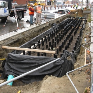
Soil cells under construction.
Soil cell installation on Central Parkway in Mississauga.
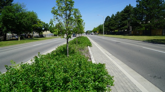
Built in 2014, this stormwater planter on Central Parkway in Mississauga uses supported soil cells and is functioning well.
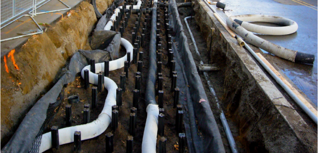
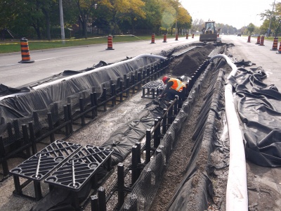
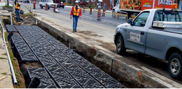
Soil Cell installation along the Moynes and Berl Avenues on north side of The Queensway in Toronto. The picture depicts stormwater distribution pipes through the system, used to help provide water to the trees that will be later planted in the BMP feature.
Photo credit: City of Toronto
Silva Cell “top” deck prior to organic layer and screenings for pavers. Photo credit: City of Toronto
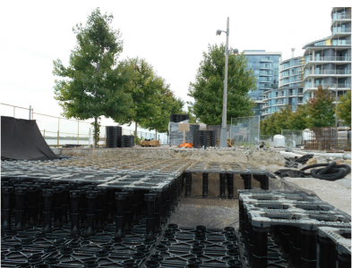
Soil Cells being installed along Edgewater Drive for Waterfront Toronto.
Photo credit: DeepRoot
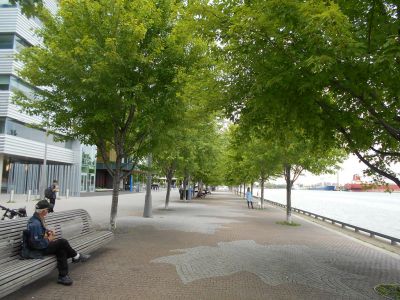
Stormwater Tree Trenches at East Bayfront Promenade, Toronto.
Photo credit: DeepRoot
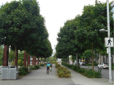
Seawall Soil Cells (Tree Trenches) located in Vancouver.
Photo credit:City of Vancouver
Stormwater tree trenches designed with a structural concrete pad over top of the installation.
Photo credit:DeepRoot


External links[edit]
- http://gievidencebase.botanicgardens.sa.gov.au/contents/7-water-management#Canopy-Interception
- standard details and specifications from James Urban
In our effort to make this guide as functional as possible, we have decided to include proprietary systems and links to manufacturers websites.
Inclusion of such links does not constitute endorsement by the Sustainable Technologies Evaluation Program.
Lists are ordered alphabetically; link updates are welcomed using the form below.
- CityGreen - Stratavault
- Contech - Filterra
- Cupolex
- Deeproot - Silva Cell
- GreenBlue Urban - RootSpace
- Storm-Tree
References[edit]
Also see references as direct web page links above.
- ↑ Crow, P. (2005). The Influence of Soils and Species on Tree Root Depth. Edinburgh. Retrieved from https://www.forestry.gov.uk/pdf/FCIN078.pdf/$FILE/FCIN078.pdf
- ↑ Wilkus A., 'Slope Style', Landscape Architecture Magazine, April 2018, accessed 21 December 2018, https://landscapearchitecturemagazine.org/2018/04/24/slope-style/
- ↑ City of Toronto. 2020. Construction Specifications and Drawings for Sewers and Watermains. https://www.toronto.ca/services-payments/building-construction/infrastructure-city-construction/construction-standards-permits/standards-for-designing-and-constructing-city-infrastructure/construction-specifications-for-sewers-and-watermains/
- ↑ City of Toronto. 2020. Construction Specifications and Drawings for Sewers and Watermains. https://www.toronto.ca/services-payments/building-construction/infrastructure-city-construction/construction-standards-permits/standards-for-designing-and-constructing-city-infrastructure/construction-specifications-for-sewers-and-watermains/