Difference between revisions of "Underdrains"
Dean Young (talk | contribs) |
Dean Young (talk | contribs) |
||
| Line 1: | Line 1: | ||
| − | Underdrains comprise a length of perforated [[pipe]] embedded into a layer of [[reservoir aggregate]]. They are an optional component of [[bioretention]] systems, [[stormwater planters]], [[ | + | Underdrains comprise a length of perforated [[pipe]] embedded into a layer of [[reservoir aggregate]]. They are an optional component of [[bioretention]] systems, [[stormwater planters]], [[bioswales]] and [[Stormwater Tree Trenches |stormwater tree trenches]]. Their design varies according to the drainage requirements of the installation, and the available maintenance access. [[Underdrain]] perforated pipes should be located below the frost line to reduce the threat of ice clogging. Ontario provincial standard drawings of frost penetration depth are available from the [https://www.library.mto.gov.on.ca/SydneyPLUS/TechPubs/Portal/tp/opsViews.aspx Ministry of Transportation] as OPSD 3090.100 for northern Ontario <ref> Ministry of Transportation. 2010. Foundation Frost Penetration Depths for Northern Ontario. OPSD 3090.100. Nov 2010. Rev.1. https://www.library.mto.gov.on.ca/SydneyPLUS/TechPubs/Portal/tp/opsViews.aspx </ref> and OPSD 3090.101 for southern Ontario <ref> Ministry of Transportation. 2010. Foundation Frost Penetration Depths for Southern Ontario. OPSD 3090.101. Nov 2010. Rev.1. https://www.library.mto.gov.on.ca/SydneyPLUS/TechPubs/Portal/tp/opsViews.aspx </ref>. |
{{TOClimit|2}} | {{TOClimit|2}} | ||
Revision as of 22:39, 30 March 2022
Underdrains comprise a length of perforated pipe embedded into a layer of reservoir aggregate. They are an optional component of bioretention systems, stormwater planters, bioswales and stormwater tree trenches. Their design varies according to the drainage requirements of the installation, and the available maintenance access. Underdrain perforated pipes should be located below the frost line to reduce the threat of ice clogging. Ontario provincial standard drawings of frost penetration depth are available from the Ministry of Transportation as OPSD 3090.100 for northern Ontario [1] and OPSD 3090.101 for southern Ontario [2].
Underdrains for infiltrating practices[edit]
The perforated pipe within the drain should be elevated from the base to promote infiltration of the water stored beneath. The depth of this internal water storage reservoir should be sized to capture and infiltrate the design storm event runoff volume based on the desired drainage time and the design infiltration rate of the native soils below. An alternative design configuration is to install the perforated pipe on the base of the practice and using an upturned outflow pipe to permit the required head of water to be stored.
- Underdrain access structures, which may be maintenance holes or vertical standpipes connected to the perforated pipe, must be included in the design for periodic inspection and flushing of the perforated pipe. Negotiating 90 degree bends will be troublesome for most push camera and jet nozzle cleaning equipment, so it is preferable that 45 degree pipe couplings be used instead.
| Pipe internal diameter (mm) | Maximum distance between cleanouts (m) |
|---|---|
| 100 | 15 |
| 200 or greater | 30 |
In some cases where the underdrain layer has sufficient depth to accommodate it, a larger diameter perforated pipe (e.g. ≥ 300 mm) may be used to add further storage capacity to a bioretention or a bioswale project. Ultimately this idea may result in the use of infiltration chambers or other void-forming structures to create significant reservoir storage beneath a bioretention filter media bed. Be sure to check with manufacturers about the compatibility of their systems with trees.
Underdrains for non-infiltrating practices[edit]
Below ground[edit]
Where a stormwater planter or biofiltration cell is contained within a concrete box or completely lined to prevent infiltration, the perforated pipe should be bedded on a thin layer of fine aggregate. This thin layer is to hold the pipe in place during construction, and to permit free ingress of accumulated water through holes on the underside of the pipe. As storage in a non-infiltrating practice is predominantly through soil/water tension, the depth of reservoir should be minimised to just accommodate the pipe. A pair of vertical clean out pipes/wells should be included in the design, for inspection and periodic flushing of accumulated sediment. As most hydro-jetting apparatus used for this has some trouble accommodating narrow 90 deg bends, it is important that both ends of a perforated pipe be connected with a pair of 45 deg elbows/Y connectors instead.
Above ground[edit]
Where possible the underdrain pipe should be designed without any bends for easy inspection and maintenance. Otherwise see advice above regarding connectors.
- To optimize water distribution and promote infiltration the base of the storage reservoir and the underdrain pipe should be graded level.
- Where drainage or conveyance to a downstream facility is a greater priority, the base of the reservoir and the underdrain pipe may have a gradient of up to 1-2%.
Maintenance and inspection[edit]


- To permit access by cameras or cleaning apparatus, 90 degree connectors must not be used in subterranean underdrains. Instead 2 x 45 degree connectors, or preferably 3 x 30 degree connectors should be used (see figure to the right).
- For the same reason, dual walled perforated pipes with smooth internal walls are highly recommended to reduce the potential snagging of maintenance equipment.
- The recommended distances between clean outs is based on advice for filter beds in the Ontario Building Code[4]. However, the access capabilities of difference apparatus and contractors varies and designers are advised to take advice from maintenance operators in this matter.
Material specifications[edit]
Pipes[edit]

Perforated pipes are a common component of underdrains used in bioretention, permeable pavements, infiltration trenches and exfiltration systems.
Pipes should be manufactured in conformity with the latest standards by the Canadian Standards Association (CSA) or ASTM International.
- Perforated pipes should be continuously perforated, smooth interior HDPE or PVC.
- Wherever possible pipes should be ≥200 mm internal diameter to reduce potential of freezing and to facilitate push camera inspections and cleaning with jet nozzle equipment.
- Smooth interior facilitates inspection and maintenance activities; internal corrugations can cause cameras or hydrojetting apparatus to become snagged.
- A perforated pipe with many rectangular slots has better drainage characteristics than a pipe with similar open area provided by fewer circular holes [5].
- Non-perforated pipes should be used for conveyance of stormwater to and from the facility, including overflow. It is good practice to extend the solid pipe approximately 300 mm within the reservoir or practice to reduce the potential for native soil migration into the pipe.
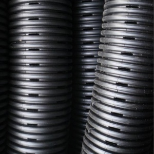
Pipe with slotted perforations
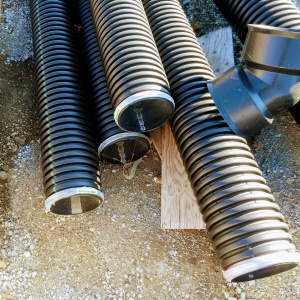
Perforated pipes awaiting installation, note the 45 degree couplings used to facilitate push camera inspection and jet nozzle cleaning.


See also: Flow through perforated pipe
Reservoir gravel[edit]
This article gives recommendations for aggregate to be used to store water for infiltration. This is usually called 'clear stone' at aggregate yards.
To see an analysis of Ontario Standard Specifications for granular materials, see OPSS aggregates.
For advice on decorative surface aggregates see Stone
Gravel used for underdrains in bioretention, infiltration trenches and chambers, and exfiltration trenches should be 20 or 50 mm, uniformly-graded, clean (maximum wash loss of 0.5%), crushed angular stone that has a porosity of 0.4[6].
The clean wash to prevent rapid accumulation of fines from the aggregate particles in the base of the reservoir. The uniform grading and the angularity are important to maintain pore throats and clear voids between particles. (i.e. achieve the porosity). Porosity and permeability are directly influenced by the size, gradation and angularity of the particles [7]. See jar test for on-site verification testing protocols.
Gravel with structural requirements should also meet the following criteria:
- Minimum durability index of 35
- Maximum abrasion of 10% for 100 revolutions and maximum of 50% for 500 revolutions
Standard specifications for the gradation of aggregates are maintained by ASTM D2940
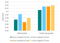
The highest porosity is found in uniformly graded aggregate, as there are no smaller particles to occupy the inter-particle pores. [7]
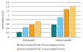
Higher permeability is found in larger, angular, uniformly graded aggregate. This is due to larger pore sizes and lower tortuosity. [7]


Choker layer[edit]

In bioretention systems a choker layer of ≥ 100 mm depth is the recommended method to prevent migration of finer filter media into the underlying storage reservoir aggregate. These same mid-sized granular materials are recommended for use in Stormwater planter underdrains and may be useful in the fine grading of foundations courses for permeable pavements.
Suitable materials include:
- High performance bedding (HPB)
- Clean, angular aggregate screened to between 6 and 10 mm. Widely available and designed specifically for drainage applications. Free from fines by definition.
- HL 6
- Is a clean, angular aggregate screened between 10 and 20 mm. Free from fines by definition.
- Pea Gravel
- Rounded natural aggregate, screened between 5 and 15 mm, and washed free from fines.
In most scenarios, a geotextile layer is unnecessary and has been associated with rapid decline and clogging in some circumstances. Geotextiles may be used to separate the underdrain from native soils on the vertical faces.
Alternative technology[edit]
Smart Drain is a polymer ribbon-like material with capillary drains on the underside; it's use has recently been demonstrated in bioretention[8]. It's low profile may make it particularly well suited to non-infiltrating practices, such as Stormwater planters.

- ↑ Ministry of Transportation. 2010. Foundation Frost Penetration Depths for Northern Ontario. OPSD 3090.100. Nov 2010. Rev.1. https://www.library.mto.gov.on.ca/SydneyPLUS/TechPubs/Portal/tp/opsViews.aspx
- ↑ Ministry of Transportation. 2010. Foundation Frost Penetration Depths for Southern Ontario. OPSD 3090.101. Nov 2010. Rev.1. https://www.library.mto.gov.on.ca/SydneyPLUS/TechPubs/Portal/tp/opsViews.aspx
- ↑ Province of Ontario. (2018). O. Reg. 332/12: BUILDING CODE. Retrieved February 23, 2018, from https://www.ontario.ca/laws/regulation/120332
- ↑ Province of Ontario. (2018). O. Reg. 332/12: BUILDING CODE. Retrieved February 23, 2018, from https://www.ontario.ca/laws/regulation/120332
- ↑ Hazenberg, G., and U. S. Panu (1991), Theoretical analysis of flow rate into perforated drain tubes, Water Resour. Res., 27(7), 1411–1418, doi:10.1029/91WR00779.
- ↑ Porosity of Structural Backfill, Tech Sheet #1, Stormtech, Nov 2012, http://www.stormtech.com/download_files/pdf/techsheet1.pdf accessed 16 October 2017
- ↑ 7.0 7.1 7.2 Judge, Aaron, "Measurement of the Hydraulic Conductivity of Gravels Using a Laboratory Permeameter and Silty Sands Using Field Testing with Observation Wells" (2013). Dissertations. 746. http://scholarworks.umass.edu/open_access_dissertations/746
- ↑ Redahegn Sileshi; Robert Pitt, P.E., M.ASCE; and Shirley Clark, P.E., M.ASCE Performance Evaluation of an Alternative Underdrain Material for Stormwater Biofiltration Systems, Journal of Sustainable Water in the Built Environment, 4(2), May 2018 https://doi.org/10.1061/JSWBAY.0000845