Difference between revisions of "Stormwater Tree Trenches"
Dean Young (talk | contribs) |
Dean Young (talk | contribs) |
||
| (13 intermediate revisions by 2 users not shown) | |||
| Line 58: | Line 58: | ||
'''Stormwater tree trench installations include:''' | '''Stormwater tree trench installations include:''' | ||
* Overlying impermeable or [[permeable pavements]] | * Overlying impermeable or [[permeable pavements]] | ||
| − | * Trees (tolerant to northern | + | * Trees (tolerant to northern urban conditions) |
* Planting soil | * Planting soil | ||
* Modular soil support or "soil cell" structures (optional) | * Modular soil support or "soil cell" structures (optional) | ||
| Line 87: | Line 87: | ||
===Infiltration=== | ===Infiltration=== | ||
For information about constraints to infiltration practices, and approaches and tools for identifying and designing within them see [[Infiltration]]. | For information about constraints to infiltration practices, and approaches and tools for identifying and designing within them see [[Infiltration]]. | ||
| − | |||
===Site Topography=== | ===Site Topography=== | ||
| Line 101: | Line 100: | ||
Maintaining a separation of 1 m between the elevations of the bottom of the trench and the seasonally high water table, or top of bedrock, is recommended. Lesser or greater values may be considered based on groundwater mounding analysis. See [[Groundwater]] for further guidance and spreadsheet tool. | Maintaining a separation of 1 m between the elevations of the bottom of the trench and the seasonally high water table, or top of bedrock, is recommended. Lesser or greater values may be considered based on groundwater mounding analysis. See [[Groundwater]] for further guidance and spreadsheet tool. | ||
| − | ===Soil=== | + | ===Native Soil=== |
| − | Tree trenches can be constructed over any soil type, but hydrologic soil group A and B are best for achieving water balance objectives. Facilities designed to infiltrate water should be located on portions of the site with the highest infiltration rates. Native soil infiltration rate at the proposed location and depth should be confirmed through in-situ measurements of hydraulic conductivity under field saturated conditions. | + | Tree trenches can be constructed over any soil type, but hydrologic soil group A and B are best for achieving water balance objectives. Facilities designed to infiltrate water should be located on portions of the site with the highest infiltration rates. Native soil infiltration rate at the proposed location and depth should be confirmed through in-situ measurements of hydraulic conductivity under field saturated conditions. For guidance on infiltration testing and selecting a design infiltration rate see [[Design infiltration rate]]. |
===Drainage Area=== | ===Drainage Area=== | ||
| − | Typical contributing drainage areas are between 150 | + | Typical contributing drainage areas are between 150 to 300 m<sup>2</sup> per tree, with a recommended maximum of 450 m<sup>2</sup> per tree. For optimal performance recommended ratios of impervious drainage area to pervious facility footprint area (I:P area ratio) range from 5:1 on low permeability soils (HSG C and D) to 15:1 on high permeability soils (HSG A and B). |
===Setback from Buildings=== | ===Setback from Buildings=== | ||
| Line 123: | Line 122: | ||
| − | For | + | For a table summarizing information on planning considerations and site constraints see [[Site considerations]]. |
==Design== | ==Design== | ||
| Line 171: | Line 170: | ||
<imagemap> | <imagemap> | ||
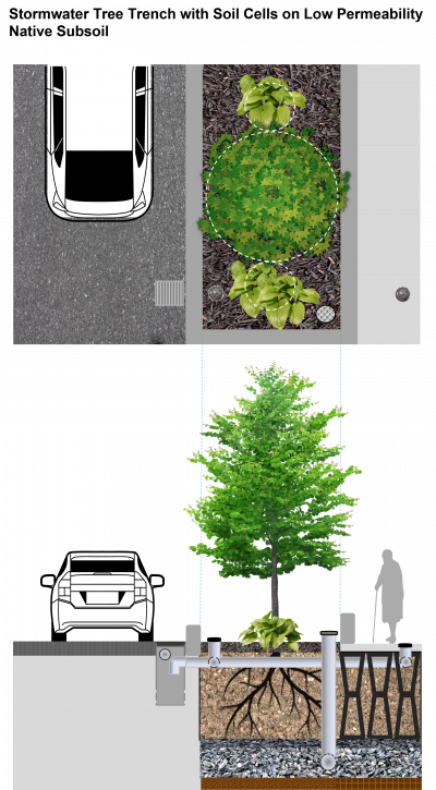
| − | File:SWTT Low Perm Soil Cells Final.png|thumb|left| | + | File:SWTT Low Perm Soil Cells Final.png|thumb|left|400px|'''Tree trench with soil cells on low permeability subsoil''' - This tree trench configuration features an overflow outlet storm sewer pipe connection in the catch basin and underdrain to allow excess water to leave the practice. The underdrain perforated pipe is embedded in the aggregate base due to the slow drainage rate of the subsoil. Solid standpipes connected to the underdrain and distribution perforated pipes provide access for inspection and maintenance tasks over the lifespan of the facility. <span style="color:red">'''''Note''': The following is an "image map", feel free to explore the image with your cursor and click on highlighted labels that appear to take you to corresponding pages on the Wiki.''</span> |
rect 1494 1440 1584 1530 [[Overflow|Overflow to Underdrain]] | rect 1494 1440 1584 1530 [[Overflow|Overflow to Underdrain]] | ||
| Line 206: | Line 205: | ||
<imagemap> | <imagemap> | ||
| − | File:SWTT High Perm Soil Cells Final.png|thumb|right| | + | File:SWTT High Perm Soil Cells Final.png|thumb|right|400px|'''Tree trench with soil cells on high permeability subsoil''' - This tree trench configuration features an overflow outlet storm sewer pipe connection in the catch basin and underdrain to allow excess water to leave the practice. The underdrain perforated pipe is embedded in the growing medium which factors in the fast drainage rate of the subsoil. A monitoring well screened within the aggregate base of the trench is included so drainage performance can be evaluated over its operating lifespan. <span style="color:red">'''''Note''': The following is an "image map", feel free to explore the image with your cursor and click on highlighted labels that appear to take you to corresponding pages on the Wiki.''</span> |
rect 1494 1440 1584 1530 [[Overflow|Overflow to Underdrain]] | rect 1494 1440 1584 1530 [[Overflow|Overflow to Underdrain]] | ||
| Line 245: | Line 244: | ||
<imagemap> | <imagemap> | ||
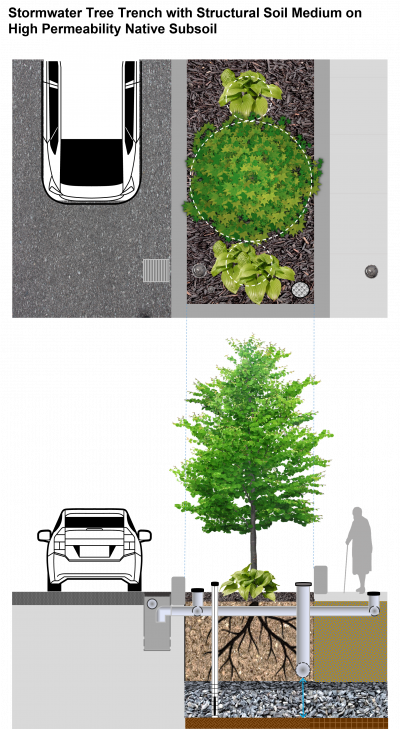
| − | File:SWTT Struct Soil Med High Perm Final.png|thumb|center| | + | File:SWTT Struct Soil Med High Perm Final.png|thumb|center|400px|'''Tree Trench with structural soil medium on high permeability subsoil''' - This tree trench configuration features structural soil medium as pavement support, as an alternative to soil cells that improves adaptability around utilities. An overflow outlet storm sewer pipe connection in the catch basin and underdrain are included to allow excess water to leave the practice. The underdrain perforated pipe is embedded in the growing medium which factors in the fast drainage rate of the subsoil. A monitoring well screened within the aggregate base of the trench is included so drainage performance can be evaluated over its operating lifespan. <span style="color:red">'''''Note''': The following is an "image map", feel free to explore the image with your cursor and click on highlighted labels that appear to take you to corresponding pages on the Wiki.''</span> |
rect 1605 3079 1983 3500 [[Stormwater Tree Trenches: Specifications|Structural Soil Medium]] | rect 1605 3079 1983 3500 [[Stormwater Tree Trenches: Specifications|Structural Soil Medium]] | ||
| Line 332: | Line 331: | ||
You can also review Urban's presentation he gave at the University of Washington in 2014 about some of the lessons learned in his book here: [https://botanicgardens.uw.edu/wp-content/uploads/sites/7/2014/10/Urban_Soils_Jim_Urban.pdf Urban Soil and Site Assessment Presentation] <ref>Urban, J. 2014. Urban Soil and Site Assessment [Presentation]. University of Washington Botanic Gardens. Seattle, WA https://botanicgardens.uw.edu/wp-content/uploads/sites/7/2014/10/Urban_Soils_Jim_Urban.pdf.</ref> | You can also review Urban's presentation he gave at the University of Washington in 2014 about some of the lessons learned in his book here: [https://botanicgardens.uw.edu/wp-content/uploads/sites/7/2014/10/Urban_Soils_Jim_Urban.pdf Urban Soil and Site Assessment Presentation] <ref>Urban, J. 2014. Urban Soil and Site Assessment [Presentation]. University of Washington Botanic Gardens. Seattle, WA https://botanicgardens.uw.edu/wp-content/uploads/sites/7/2014/10/Urban_Soils_Jim_Urban.pdf.</ref> | ||
| − | ==Inspection and | + | ==Inspection and Maintenance== |
Tree trenches have fewer maintenance requirements than bioretention cells or bioswales, but maintenance is still critical to their success. The most critical maintenance task is the removal of trash, sediment and debris accumulated in inlet structure sumps, gravel diaphragms and tree openings at curb cuts. This should be done at least once per year, however the frequency will depend on pavement uses, traffic volumes and tree canopy size. Inspect new trenches closely during the first two years of operation to measure the rate of accumulation and set an optimal maintenance frequency. | Tree trenches have fewer maintenance requirements than bioretention cells or bioswales, but maintenance is still critical to their success. The most critical maintenance task is the removal of trash, sediment and debris accumulated in inlet structure sumps, gravel diaphragms and tree openings at curb cuts. This should be done at least once per year, however the frequency will depend on pavement uses, traffic volumes and tree canopy size. Inspect new trenches closely during the first two years of operation to measure the rate of accumulation and set an optimal maintenance frequency. | ||
| Line 340: | Line 339: | ||
See further details here: [[Stormwater Tree Trenches: Maintenance]] | See further details here: [[Stormwater Tree Trenches: Maintenance]] | ||
| + | |||
| + | <br> | ||
| + | |||
| + | Also take a look at the [[Inspection and Maintenance: Bioretention & Bioswales]] page by clicking below for further details about proper inspection and maintenance practices: | ||
| + | |||
| + | {{Clickable button|[[File:Cover Photo.PNG|150 px|link=https://wiki.sustainabletechnologies.ca/wiki/Inspection_and_Maintenance:_Bioretention_%26_Bioswales]]}} | ||
==Performance== | ==Performance== | ||
| Line 367: | Line 372: | ||
</br> | </br> | ||
{|class="wikitable" | {|class="wikitable" | ||
| − | |+Volumetric runoff reduction from | + | |+Volumetric runoff reduction from Stormwater Tree Trench/Bioretention |
|- | |- | ||
!'''LID Practice''' | !'''LID Practice''' | ||
| Line 375: | Line 380: | ||
|- | |- | ||
|rowspan="4" style="text-align: center;" | Bioretention without underdrain | |rowspan="4" style="text-align: center;" | Bioretention without underdrain | ||
| + | |style="text-align: center;" |China | ||
| + | |style="text-align: center;" |'''<u><span title="Note: Runoff reduction estimates are based on SWMM and RECARGA models applied to generate the runoff reduction percentages of a bioretention installation near one of China's and expressway service area.">85 to 100%*</span></u>''' | ||
| + | |style="text-align: center;" |Gao, ''et al.'' (2018)<ref>Gao, J., Pan, J., Hu, N. and Xie, C., 2018. Hydrologic performance of bioretention in an expressway service area. Water Science and Technology, 77(7), pp.1829-1837.</ref> | ||
| + | |- | ||
|style="text-align: center;" |Connecticut | |style="text-align: center;" |Connecticut | ||
|style="text-align: center;" |99% | |style="text-align: center;" |99% | ||
| Line 386: | Line 395: | ||
|style="text-align: center;" |70% | |style="text-align: center;" |70% | ||
|style="text-align: center;" |Emerson and Traver (2004)<ref>Emerson, C., Traver, R. 2004. The Villanova Bio-infiltration Traffic Island: Project Overview. Proceedings of 2004 World Water and Environmental Resources Congress (EWRI/ASCE). Salt Lake City, Utah, June 22 – July 1, 2004. https://ascelibrary.org/doi/book/10.1061/9780784407370</ref> | |style="text-align: center;" |Emerson and Traver (2004)<ref>Emerson, C., Traver, R. 2004. The Villanova Bio-infiltration Traffic Island: Project Overview. Proceedings of 2004 World Water and Environmental Resources Congress (EWRI/ASCE). Salt Lake City, Utah, June 22 – July 1, 2004. https://ascelibrary.org/doi/book/10.1061/9780784407370</ref> | ||
| − | |||
| − | |||
| − | |||
| − | |||
|- | |- | ||
|rowspan="8" style="text-align: center;" | Bioretention with underdrain | |rowspan="8" style="text-align: center;" | Bioretention with underdrain | ||
| Line 396: | Line 401: | ||
|style="text-align: center;" |'''<u><span title="Note: Runoff reduction estimates are based on differences in runoff volume between the practice and a conventional impervious surface over the period of monitoring.">82%*</span></u>''' | |style="text-align: center;" |'''<u><span title="Note: Runoff reduction estimates are based on differences in runoff volume between the practice and a conventional impervious surface over the period of monitoring.">82%*</span></u>''' | ||
|style="text-align: center;" |Mahmoud, ''et al.'' (2019)<ref>Mahmoud, A., Alam, T., Rahman, M.Y.A., Sanchez, A., Guerrero, J. and Jones, K.D. 2019. Evaluation of field-scale stormwater bioretention structure flow and pollutant load reductions in a semi-arid coastal climate. Ecological Engineering, 142, p.100007. https://www.sciencedirect.com/science/article/pii/S2590290319300070</ref> | |style="text-align: center;" |Mahmoud, ''et al.'' (2019)<ref>Mahmoud, A., Alam, T., Rahman, M.Y.A., Sanchez, A., Guerrero, J. and Jones, K.D. 2019. Evaluation of field-scale stormwater bioretention structure flow and pollutant load reductions in a semi-arid coastal climate. Ecological Engineering, 142, p.100007. https://www.sciencedirect.com/science/article/pii/S2590290319300070</ref> | ||
| + | |- | ||
| + | |style="text-align: center;" |China | ||
| + | |style="text-align: center;" |'''<u><span title="Note: Runoff reduction estimates are based on SWMM and RECARGA models applied to generate the runoff reduction percentages of a bioretention installation near one of China's and expressway service area.">35 to 75%*</span></u>''' | ||
| + | |style="text-align: center;" |Gao, ''et al.'' (2018)<ref>Gao, J., Pan, J., Hu, N. and Xie, C., 2018. Hydrologic performance of bioretention in an expressway service area. Water Science and Technology, 77(7), pp.1829-1837.</ref> | ||
| + | |- | ||
| + | |style="text-align: center;" |Ohio | ||
| + | |style="text-align: center;" |36 to 59% | ||
| + | |style="text-align: center;" |Winston ''et al.'' (2016). <ref>Winston, R.J., Dorsey, J.D. and Hunt, W.F. 2016. Quantifying volume reduction and peak flow mitigation for three bioretention cells in clay soils in northeast Ohio. Science of the Total Environment, 553, pp.83-95.</ref> | ||
|- | |- | ||
|style="text-align: center;" |Virginia | |style="text-align: center;" |Virginia | ||
| Line 401: | Line 414: | ||
|style="text-align: center;" |DeBusk and Wynn (2011)<ref>DeBusk, K.M. and Wynn, T.M., 2011. Storm-water bioretention for runoff quality and quantity mitigation. Journal of Environmental Engineering, 137(9), pp.800-808. https://www.webpages.uidaho.edu/ce431/Articles/DeBusk-ASCE-2011.pdf</ref> | |style="text-align: center;" |DeBusk and Wynn (2011)<ref>DeBusk, K.M. and Wynn, T.M., 2011. Storm-water bioretention for runoff quality and quantity mitigation. Journal of Environmental Engineering, 137(9), pp.800-808. https://www.webpages.uidaho.edu/ce431/Articles/DeBusk-ASCE-2011.pdf</ref> | ||
|- | |- | ||
| − | |style="text-align: center;" | | + | |style="text-align: center;" |Maryland and North Carolina |
| − | |style="text-align: center;" | | + | |style="text-align: center;" |20 to 50% |
| − | |style="text-align: center;" | | + | |style="text-align: center;" |Li ''et al.'' (2009). <ref>Li, H., Sharkey, L.J., Hunt, W.F., and Davis, A.P. 2009. Mitigation of Impervious Surface Hydrology Using Bioretention in North Carolina and Maryland. Journal of Hydrologic Engineering. Vol. 14. No. 4. pp. 407-415.</ref> |
|- | |- | ||
|style="text-align: center;" |North Carolina | |style="text-align: center;" |North Carolina | ||
| Line 412: | Line 425: | ||
|style="text-align: center;" |33 to 50% | |style="text-align: center;" |33 to 50% | ||
|style="text-align: center;" |Hunt and Lord (2006). <ref>Hunt, W.F. and Lord, W.G. 2006. Bioretention Performance, Design, Construction, and Maintenance. North Carolina Cooperative Extension Service Bulletin. Urban Waterways Series. AG-588-5. North Carolina State University. Raleigh, NC.</ref> | |style="text-align: center;" |Hunt and Lord (2006). <ref>Hunt, W.F. and Lord, W.G. 2006. Bioretention Performance, Design, Construction, and Maintenance. North Carolina Cooperative Extension Service Bulletin. Urban Waterways Series. AG-588-5. North Carolina State University. Raleigh, NC.</ref> | ||
| − | |||
| − | |||
| − | |||
| − | |||
| − | |||
| − | |||
| − | |||
| − | |||
|- | |- | ||
|rowspan="5" style="text-align: center;" | Bioretention with underdrain & liner | |rowspan="5" style="text-align: center;" | Bioretention with underdrain & liner | ||
| Line 426: | Line 431: | ||
|style="text-align: center;" |15 to 34% | |style="text-align: center;" |15 to 34% | ||
|style="text-align: center;" |<span class="plainlinks">[https://sustainabletechnologies.ca/app/uploads/2019/10/STEP_Bioretention-Synthesis_Tech-Brief-New-Template-2019-Oct-10.-2019.pdf STEP (2019)]</span> <ref>STEP. 2019. Comparative Performance Assessment of Bioretention in Ontari0. Technical Brief. https://sustainabletechnologies.ca/app/uploads/2019/10/STEP_Bioretention-Synthesis_Tech-Brief-New-Template-2019-Oct-10.-2019.pdf.</ref> | |style="text-align: center;" |<span class="plainlinks">[https://sustainabletechnologies.ca/app/uploads/2019/10/STEP_Bioretention-Synthesis_Tech-Brief-New-Template-2019-Oct-10.-2019.pdf STEP (2019)]</span> <ref>STEP. 2019. Comparative Performance Assessment of Bioretention in Ontari0. Technical Brief. https://sustainabletechnologies.ca/app/uploads/2019/10/STEP_Bioretention-Synthesis_Tech-Brief-New-Template-2019-Oct-10.-2019.pdf.</ref> | ||
| − | |||
| − | |||
| − | |||
| − | |||
|- | |- | ||
|style="text-align: center;" |Queensland, Australia | |style="text-align: center;" |Queensland, Australia | ||
| Line 438: | Line 439: | ||
|style="text-align: center;" |15 to 83% | |style="text-align: center;" |15 to 83% | ||
|style="text-align: center;" |Hatt ''et al.'' (2009). <ref>Hatt, B. E., Fletcher, T. D., & Deletic, A. 2009. Hydrologic and pollutant removal performance of stormwater biofiltration systems at the field scale. Journal of Hydrology, 365(3), 310-321. doi:http://dx.doi.org/10.1016/j.jhydrol.2008.12.001</ref> | |style="text-align: center;" |Hatt ''et al.'' (2009). <ref>Hatt, B. E., Fletcher, T. D., & Deletic, A. 2009. Hydrologic and pollutant removal performance of stormwater biofiltration systems at the field scale. Journal of Hydrology, 365(3), 310-321. doi:http://dx.doi.org/10.1016/j.jhydrol.2008.12.001</ref> | ||
| + | |- | ||
| + | |style="text-align: center;" |Maryland | ||
| + | |style="text-align: center;" |49 to 58% | ||
| + | |style="text-align: center;" |Davis (2008). <ref>Davis, A.P. 2008. Field performance of bioretention: Hydrology impacts. Journal of hydrologic engineering, 13(2), pp.90-95. https://ascelibrary.org/doi/abs/10.1061/(ASCE)1084-0699(2008)13:2(90)</ref> | ||
|- | |- | ||
| colspan="2" style="text-align: center;" |'''<u><span title="Note: This estimate is provided only for the purpose of initial screening of LID practices suitable for achieving stormwater management objectives and targets. Performance of individual facilities will vary depending on site specific contexts and facility design parameters and should be estimated as part of the design process and submitted with other documentation for review by the approval authority." >Runoff Reduction Estimate*</span></u>''' | | colspan="2" style="text-align: center;" |'''<u><span title="Note: This estimate is provided only for the purpose of initial screening of LID practices suitable for achieving stormwater management objectives and targets. Performance of individual facilities will vary depending on site specific contexts and facility design parameters and should be estimated as part of the design process and submitted with other documentation for review by the approval authority." >Runoff Reduction Estimate*</span></u>''' | ||
| Line 451: | Line 456: | ||
For other recent research on the water management benefits of urban trees, and modelling approaches see the following articles and projects. | For other recent research on the water management benefits of urban trees, and modelling approaches see the following articles and projects. | ||
| + | * '''[https://www.sciencedirect.com/science/article/abs/pii/S0048969721063749?via%3Dihub Stormwater runoff volume reduction benefits of urban street tree canopy (Selbig et al., 2022)]''' <ref> Selbig, W.R., Loheide II, S.P., Shuster, W., Scharenbroch, B.C., Coville, R.C., Kruegler, J., Avery, W., Haefner, R., Nowak, D. Quantifying stormwater runoff volume reduction benefit of urban street tree canopy. Science of the Total Environment. v.806 (2022) 151296. https://www.sciencedirect.com/science/article/abs/pii/S0048969721063749?via%3Dihub </ref> | ||
| + | ** In a paired-catchment study design involving medium density residential areas in Wisconsin, with removal of 29 mature green ash and Norway maple street trees as the treatment, tree removal resulted in a 4% increase in runoff volume over the evaluation period, while peak discharge was generally not affected. Runoff volume reduction benefit of the street tree canopy was estimated at 6376 L per tree, which is similar to values reported in previous studies based largely on simulation. | ||
* '''[https://open.library.ubc.ca/soa/cIRcle/collections/ubctheses/24/items/1.0378388 Stormwater tree trench and bioswale performance in Vancouver, BC (Vega 2019)]''' <ref> Vega, O.M. Green infrastructure in the City of Vancouver: performance monitoring of stormwater tree trenches and bioswales. UBC Theses and Dissertations. https://open.library.ubc.ca/soa/cIRcle/collections/ubctheses/24/items/1.0378388 </ref> | * '''[https://open.library.ubc.ca/soa/cIRcle/collections/ubctheses/24/items/1.0378388 Stormwater tree trench and bioswale performance in Vancouver, BC (Vega 2019)]''' <ref> Vega, O.M. Green infrastructure in the City of Vancouver: performance monitoring of stormwater tree trenches and bioswales. UBC Theses and Dissertations. https://open.library.ubc.ca/soa/cIRcle/collections/ubctheses/24/items/1.0378388 </ref> | ||
** A study of a stormwater tree trench featuring structural soil medium and two bioswales in Vancouver, British Columbia found that these practices are effective in treating heavy metals, suspended solids and other typical stormwater pollutants, and are effective tools for reducing runoff volume by promoting infiltration to native soils. | ** A study of a stormwater tree trench featuring structural soil medium and two bioswales in Vancouver, British Columbia found that these practices are effective in treating heavy metals, suspended solids and other typical stormwater pollutants, and are effective tools for reducing runoff volume by promoting infiltration to native soils. | ||
Revision as of 20:40, 14 April 2023
Overview[edit]
Stormwater tree trenches are linear tree planting structures that feature supported impermeable or permeable pavements that promote healthy tree growth while also helping to manage runoff. They are often located behind the curb within the road right-of-way and consist of subsurface trenches filled with modular structures and growing medium, or structurally engineered soil medium, supporting an overlying sidewalk pavement. They improve tree health by providing access to soil, air and stormwater for irrigation, allowing them to survive longer in harsh urban conditions.
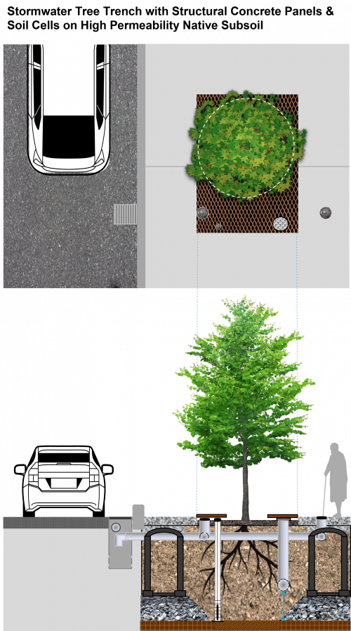
They also provide road and walkway drainage, contribute to stormwater pollutant removal and decrease the volume of urban runoff entering local waterways. They feature trees, soil, stormwater inlet and outlet structures, distribution and drainage pipes, and may include soil support structures, structural soil medium or structural concrete panels (as seen in the image map to the right). The tree planting pits and adjacent supported sidewalk pavements provide more soil volume for tree growth and water retention.
Take a look at the downloadable Stormwater Tree Trench Fact Sheet below for a .pdf overview of this LID Best Management Practice:

Stormwater tree trench installations include:
- Overlying impermeable or permeable pavements
- Trees (tolerant to northern urban conditions)
- Planting soil
- Modular soil support or "soil cell" structures (optional)
- Structural soil (optional)
- Structural concrete panels (optional)
- Stormwater inlet and outlet structures
- Distribution and drainage pipes
- Choker layer (optional)
- Geogrid and geotextile (optional)
- Aggregate base
Stomwater tree trenches are ideal for:
- Sites with limited space for other surface stormwater BMPs that also possess primarily impermeable coverage (i.e. a municipality's "right-of-way", which includes the edge between private/public property, roadways, sidewalks and utility service land use)
- Areas with limited greenspace
- Projects with high traffic loads (pedestrian and vehicular), laneways, pedestrian plazas and walkways
Additional components may include:
- Internal water storage layer
- Distribution and underdrain pipe access and clean-out features
- Monitoring well screened within internal water storage layer
- Root barriers in locations where tree rooting is not desired
Planning considerations[edit]
A commonly held view is that a tree's root system will be similar to it's visible crown. For many trees, this is not the case, as roots will more often spread much more widely, but to a shallower depth [1].
Infiltration[edit]
For information about constraints to infiltration practices, and approaches and tools for identifying and designing within them see Infiltration.
Site Topography[edit]
Contributing slopes should be between 1-5%. The bottom of the trench and distribution pipes should be graded flat to allow water to spread out.
Planting in slopes[edit]
Smooth slopes should be amended into localized terraces by the Landscape Architect when planting large trees into slopes > 5 %. [2]. Contributing slopes should be between 1-5%. The bottom of the trench and distribution pipes should be graded flat to allow water to spread out.
Wellhead Protection[edit]
Facilities receiving road or parking lot runoff should not be located within 2 year time-of-travel wellhead protection areas.
Water Table[edit]
Maintaining a separation of 1 m between the elevations of the bottom of the trench and the seasonally high water table, or top of bedrock, is recommended. Lesser or greater values may be considered based on groundwater mounding analysis. See Groundwater for further guidance and spreadsheet tool.
Native Soil[edit]
Tree trenches can be constructed over any soil type, but hydrologic soil group A and B are best for achieving water balance objectives. Facilities designed to infiltrate water should be located on portions of the site with the highest infiltration rates. Native soil infiltration rate at the proposed location and depth should be confirmed through in-situ measurements of hydraulic conductivity under field saturated conditions. For guidance on infiltration testing and selecting a design infiltration rate see Design infiltration rate.
Drainage Area[edit]
Typical contributing drainage areas are between 150 to 300 m2 per tree, with a recommended maximum of 450 m2 per tree. For optimal performance recommended ratios of impervious drainage area to pervious facility footprint area (I:P area ratio) range from 5:1 on low permeability soils (HSG C and D) to 15:1 on high permeability soils (HSG A and B).
Setback from Buildings[edit]
Tree trenches should be set back from the building far enough to allow for the tree canopy to grow to a healthy, mature size, depending on the species selected. A minimum setback of 4 m from buildings is recommended.
Overhead Wires[edit]
Tree trenches should be implemented with caution under overhead wires. If overhead wires conflict with proposed tree trench locations, check the height of existing wires, and choose small form trees that will not grow tall enough to interfere with wires.
Pollution Hot Spot Runoff[edit]
Tree trenches receiving road or parking lot runoff are not recommended in these areas.
Proximity to Underground Utilities[edit]
Designers should consult local utility design guidance for the horizontal and vertical clearances required.
Karst[edit]
Tree trenches designed to drain primarily by infiltration are unsuitable in areas of known or implied karst topography.
For a table summarizing information on planning considerations and site constraints see Site considerations.
Design[edit]

Things to consider in design:
- If the trench is unlined it is hydraulically similar to a full- or partial-infiltration design bioretention cell and should provide similar water quality benefits.
- If the trench features an impermeable liner and underdrain it is hydraulically similar to a large stormwater planter or no-infiltration design bioretention cell and should provide similar water quality benefits.
- Depending on design details tree trenches may retain a significant volume of stormwater within the planting soil and internal water storage layer and provide runoff volume reduction benefit.
Geometry and Site Layout[edit]
Tree trenches are continuous, linear urban tree planting systems, often located behind the curb within the road right-of-way and feature sidewalk pavement and tree openings on top. Trench sections are connected hydrologically through sub-surface stormwater distribution and drainage pipes.
Inlets[edit]
Water can enter the tree trench in a variety of ways: from the overlying sidewalk via sheet flow or curb cuts into tree openings, trench drains, or infiltration through permeable pavement; and from the road via distribution pipes connected to road or side inlet catch basins and curb cuts or depressed drains at tree openings. It is recommended that each tree trench have multiple inlets to keep the contributing drainage area relatively small, which provides redundancy to the system. Inlet structures and distribution pipes should be offset from tree root ball locations to avoid impact of de-icing salt laden runoff on newly planted trees during establishment.
Pre-Treatment[edit]
If water enters the trench via a catch basin, a removable pre-treatment device, like a Goss trap or proprietary catch basin insert device or filter should be included to help retain coarse sediment, debris and floatables and prevent it from entering the pipe or trench. Inlet structures should have a sump and curb cut inlets should include stone diaphragms or stone mulch to dissipate energy and spread flows. Pre-treatment features should be easy to access and clean out.
Soil Volume[edit]
Each tree planted should have access to a minimum 30 m3 of soil volume, including the growing medium within the tree pit and growing or structural soil medium below adjacent supported pavement. If more than one tree shares the same trench a minimum 20 m3 of soil per tree may be acceptable.
Modular Soil Support Systems[edit]
Modular soil support systems (also referred to as “soil cells”) consist of plastic or concrete structures, available in a variety of shapes and sizes, that provide structural support for the overlying pavement while providing uncompacted planting soil within the tree root zone. They are installed adjacent to tree pits to provide room for roots to spread out under the supported pavement portion of the trench. Growing medium backfill typically has higher organic matter content than structural soil medium. The looser structure and higher nutrient content of the growing medium provides the most favorable environment for healthy tree growth in an urban setting. Critical to modular soil support system design is that each structure or layer of structures be independent of all adjacent ones, such that one or multiple layers can be removed to facilitate future utility installation or repair.

Structural Soil Medium[edit]
Structural soil is an engineered soil medium that can be compacted to support sidewalk or roadway pavement installation requirements while also permitting tree root growth. Structural soil medium filled trenches are installed adjacent to tree pits to provide room for tree roots to spread out under the supported pavement portion of the tree trench.
Structural Concrete Panels[edit]
Trenches where the overlying sidewalk pavement consists of reinforced structural concrete panels is another configuration. Panels are supported on each side by concrete footings and rows of modular soil support structures or structural soil medium, installed on aggregate bases. The benefit of this approach is that the native subgrade soil under the portions of the trench below tree pits and between rows of supports does not need to be highly compacted, allowing greater opportunity for drainage via infiltration. (see image map within the 'Overview' section of this page).
Conveyance and Overflow[edit]
Runoff is directed from overlying and adjacent pavements to the trench through such means as tree openings, perforated distribution pipes connected to catchbasins or trench drains, or curb cuts and depressed drains to tree openings. Runoff water percolates through the growing or structural soil medium to the underlying native subgrade soil. When runoff volume exceeds the trench water storage capacity, the perforated underdrain pipe directs excess filtered water to a downstream outlet storm sewer or other practice. During intense storm events, runoff in excess of the infiltration capacity of the growing or structural soil medium will overflow to the storm sewer either through an outlet pipe connection in the catch basin or via surface overflow standpipes or structures within tree openings.
Configuration[edit]
Modular soil support system and structural concrete panel trench configurations should provide a better growing environment for trees, and thereby improve tree longevity. Structural soil medium and structural concrete panel trench configurations provide the benefits of being more adaptable around utilities and existing trees and providing easier access to utilities when repairs are needed. Structural concrete panel trench configurations featuring rows of modular soil supports provide greater soil volume per unit area than those featuring structural soil medium.
Distribution and Underdrain pipes[edit]
To maximize the quantity of growing or structural soil medium irrigated, distribution pipes should be installed flat, just below modular soil support tops or at the top of the structural soil media layer and in both tree pit and supported pavement portions of the trench. Pipe perforations should be oriented to the sides and section ends should be sealed with a solid cap. To enhance runoff volume reduction underdrain pipes can be installed above the bottom of the trench and/or include flow control. Alternatively, the underdrain pipe may be installed on trench bottom and connected to a riser assembly in the outlet manhole. It is critical to include connections to outlet storm sewer pipes and multiple cleanout access points.
Variations of Stormwater Tree Trenches[edit]
Below, find three alternate stormwater tree trench design configurations that differ by native subgrade soil permeability, structural support systems used (modular soil cell systems vs. structural soil medium) and elevation of the underdrain perforated pipe in the cross-section based on subgrade soil permeability.

| Material | Specification |
|---|---|
| Growing Medium |
|
| Modular Soil Support System |
|
| Structural Soil Medium |
|
| Structural Concrete Panel |
|
| Aggregate Base |
|
| Geotextile & Geogrid |
|
| Underdrain |
|
| Stormwater Distribution Pipe |
|
Benefits of trees[edit]
Stormwater tree trenches help support healthy street trees in urban settings where conventional plantings have limited space for root establishment. Trees play a critical role in stormwater management from reducing runoff through canopy interception, evapotranspiration, filtering out pollutants, and increasing infiltration capacity of soils, to retaining runoff.[5], [6] Trees also provide a myriad other environmental benefits, from shading impervious surfaces and thereby reducing urban heat island effects, to providing wildlife habitat and improving the aesthetics of streets and neighbourhoods. Research has shown that healthy trees increase property values, retail spending and contribute to a sense of community pride and safety.
Below is a list of trees that are known to tolerate conditions in northern (Zone 3) urban stormwater tree trenches.
| Latin Name | Common Name |
|---|---|
| Ulmus americana | American Elm |
| Acer x freemanii | Freeman’s Maple |
| Alnus incana | White Alder |
| Celtis occidentalis | Hackberry |
| Gleditsia triacanthos var. inermis | Thornless Honeylocust |
| Gymnocladus dioicus | Kentucky Coffeetree |
| Quercus bicolor | White Oak |
| Quercus macrocarpa | Bur Oak |
| Quercus rubra | Red Oak |
Species selection[edit]
For an overview of key considerations affecting planting plans and tree species selection please visit our planting design, plant selection and tree species wiki pages that provide guidance to help you develop functional and attractive planting plans.
Tree planting best practices[edit]
An extensive compendium of recommended standard tree planting details and specifications are available from James Urban.
See the figure below that depicts the relationship between soil volume, water storage volume provided by the soil volume, and tree size from James Urban's (2008) book, entitled "Up by Roots" [7]

You can also review Urban's presentation he gave at the University of Washington in 2014 about some of the lessons learned in his book here: Urban Soil and Site Assessment Presentation [8]
Inspection and Maintenance[edit]
Tree trenches have fewer maintenance requirements than bioretention cells or bioswales, but maintenance is still critical to their success. The most critical maintenance task is the removal of trash, sediment and debris accumulated in inlet structure sumps, gravel diaphragms and tree openings at curb cuts. This should be done at least once per year, however the frequency will depend on pavement uses, traffic volumes and tree canopy size. Inspect new trenches closely during the first two years of operation to measure the rate of accumulation and set an optimal maintenance frequency.
Underdrains and distribution pipes within the tree trench must be designed for ease of maintenance. Pipe couplings should be no greater than 45 degrees to allow inspection and cleaning equipment to access it, with enough cleanout access standpipes or structures to access the full length of the pipe.
Tree care is also an important part of tree trench maintenance. Provide regular irrigation and weed control in the tree openings until newly planted trees are fully established. Prune trees as needed once established to prevent safety hazards to pedestrians, overhead utility lines, and adjacent buildings. Monitor trees for damage by insects and other pests and replace trees that are in decline. A tree trench containing a diseased or dying tree is not a fully functional practice.
See further details here: Stormwater Tree Trenches: Maintenance
Also take a look at the Inspection and Maintenance: Bioretention & Bioswales page by clicking below for further details about proper inspection and maintenance practices:

Performance[edit]
In a proof-of-concept study of two stormwater tree trenches in Wilmington, North Carolina, Page et al. (2015) found that the soil-root matrix beneath the supported pavements can be used for stormwater control to achieve runoff volume reduction (80% over a yearlong evaluation period), pollutant retention, pavement stability and urban forestry goals.[9] To read about the use of stormwater tree trenches featuring soil cells in the Greater Toronto Area see the STEP technical brief and case study on the Queensway Sustainable Sidewalk Pilot Project in the City of Toronto. Evaluations of the project found that stormwater tree trenches are able to increase the urban street tree canopy coverage while requiring minimal surface area below, and provide stormwater benefits associated with TSS and heavy metal contaminant removal and runoff volume reduction, with lower routine maintenance costs than other surface practices like bioretention. [10] [11] In a hydrologic study of the Queensway Sustainable Sidewalk project, Li et al. (2020) highlight the importance of inlet hydraulics and spatial distribution of inflow along the stormwater tree trench and propose an integrated modelling approach to simulate overall runoff control performance. [12] Also see Credit Valley Conservation Central Parkway LID case study and technical report that summarize findings from evaluation of a stormwater tree trench featuring soil cells located in the median of a high-traffic road in Mississauga, Ontario. Monitoring showed the stormwater tree trench performed well over the eight storm events monitored with an average runoff volume reduction of 97%, and peak flow reduction of 96%. [13] [14]
| BMP | Water Balance | Water Quality | Erosion Control |
|---|---|---|---|
| Stormwater Tree Trench |
|
|
|
| LID Practice | Location | Runoff Reduction* | Reference |
|---|---|---|---|
| Bioretention without underdrain | China | 85 to 100%* | Gao, et al. (2018)[15] |
| Connecticut | 99% | Dietz and Clausen (2005) [16] | |
| Pennsylvania | 80% | Ermilio (2005)[17] | |
| Pennsylvania | 70% | Emerson and Traver (2004)[18] | |
| Bioretention with underdrain | |||
| Texas | 82%* | Mahmoud, et al. (2019)[19] | |
| China | 35 to 75%* | Gao, et al. (2018)[20] | |
| Ohio | 36 to 59% | Winston et al. (2016). [21] | |
| Virginia | 97 to 99% | DeBusk and Wynn (2011)[22] | |
| Maryland and North Carolina | 20 to 50% | Li et al. (2009). [23] | |
| North Carolina | 40 to 60% | Smith and Hunt (2007)[24] | |
| North Carolina | 33 to 50% | Hunt and Lord (2006). [25] | |
| Bioretention with underdrain & liner | |||
| Ontario | 15 to 34% | STEP (2019) [26] | |
| Queensland, Australia | 33 to 84% | Lucke and Nichols (2015). [27] | |
| Victoria, Australia | 15 to 83% | Hatt et al. (2009). [28] | |
| Maryland | 49 to 58% | Davis (2008). [29] | |
| Runoff Reduction Estimate* | 85% without underdrain;
45% with underdrain | 30% with underdrain and liner | ||
Performance research[edit]
Tree canopies influence various components of the urban hydrologic cycle. Water losses occur via canopy interception and evaporation, transpiration, improved soil infiltration and percolation along root channels, and water table management, thereby attenuating stormwater runoff and reducing demands on drainage infrastructure. Canopy interception loss is relevant during and immediately after a storm event, while transpiration plays a role in managing soil moisture over the days and weeks between events. Canopy interception contributes to runoff volume reduction, delays the onset of peak flows and helps protect water quality. Urban tree canopy interception and evaporation rates vary according to canopy type (e.g., closed vs. open), tree species attributes, season, and storm characteristics (e.g., rainfall intensity, duration and time between events). Berland et al. (2017), call for greater consideration of arboriculture as a stormwater control measure in their literature review, noting that trees are compatible with various types of LID facilities and may improve the function of these installations through evapotranspiration and maintaining or improving drainage performance.[30] In a study of twenty tree species in Davis, California, Xiao and McPherson (2016) found that conifers generally stored more water than broadleaf deciduous species and that leaf surfaces have larger capacities to store rainfall than stem surfaces. [31] Tree species with large mature sizes and high stomatal conductance (e.g., Quercus macrocarpa, bur oak) were shown to markedly improve the function of parking lot bioretention swales in the City of Chicago, Illinois. [32]
For other recent research on the water management benefits of urban trees, and modelling approaches see the following articles and projects.
- Stormwater runoff volume reduction benefits of urban street tree canopy (Selbig et al., 2022) [33]
- In a paired-catchment study design involving medium density residential areas in Wisconsin, with removal of 29 mature green ash and Norway maple street trees as the treatment, tree removal resulted in a 4% increase in runoff volume over the evaluation period, while peak discharge was generally not affected. Runoff volume reduction benefit of the street tree canopy was estimated at 6376 L per tree, which is similar to values reported in previous studies based largely on simulation.
- Stormwater tree trench and bioswale performance in Vancouver, BC (Vega 2019) [34]
- A study of a stormwater tree trench featuring structural soil medium and two bioswales in Vancouver, British Columbia found that these practices are effective in treating heavy metals, suspended solids and other typical stormwater pollutants, and are effective tools for reducing runoff volume by promoting infiltration to native soils.
- Stormwater infiltration capacity of street tree pits in New York City (Elliott et al. 2018) [35]
- In a study of forty tree pits representing typical varieties of physical conditions in New York City, Elliott et al. found the most significant factor influencing infiltration rate was the presence of fencing or guard rails, with guarded tree pits having higher infiltration rates. Additionally, higher infiltration rates were associated with larger tree pit areas, built-up surface elevations and the combined presence of ground cover plantings and mulch.
- Tree pit hydrology in Melbourne, Australia (Grey et al. 2018) [36]
- Grey et al. (2018), conducted a streetscape experiment to determine the runoff retention rate of tree pits in heavy clay soil with low exfiltration rates. Their research found that runoff retention is possible in even very dense urban streetscapes, and that sizing needs to be between 2.5% to 8% of the impervious catchment area (dependent upon tree pit exfiltration rates) to achieve 90% reduction in annual runoff.
- Health of trees in bioretention (Tirpak et al. 2018)[37]
- Tirpak et al. (2018), conducted a study on tree health in bioretention systems in southeastern U.S. Of the 6 species studied, only 1 showed greater health when grown in bioretention media compared to urban trees not planted in bioretention systems. Results show that species selection should be based on bioretention filter media analysis and compatability with the growing conditions found in bioretention systems.
- Review of stormwater benefits of urban trees (Kuehler et al. 2017)[38]
- Kuehler, et al. (2017) in their literature review found that urban trees can retain sizable amounts of annual rainfall in their crowns, delay the flow of stormwater runoff, substantially increase the infiltration capacity of urban soils, and provide transpiration of sequestered runoff. Tree canopy effectiveness is highest during short, low‐intensity storms and lower as rainfall volume and intensity increases.
- Estimating tree leaf area density with LIDAR (Li et al. 2017)[39]
- Li, et al. (2017), determine an effective means for leaf area density (LAD) estimation of a canopy of magnolia trees using high-resolution LiDAR data and ground measured leaf area index (LAI).
- Modelling rainfall interception by urban trees (Huang et al. 2017)[40]
- Huang, et al. (2017), developed an analytical model to compare rainfall interception rates between four deciduous tree species (white oak, Norway maple, green ash and cherry). The ratio of evaporation rate to rainfall rate was the most dynamic differing parameter amongst the trees selected. The study was able to provide some information on improved tree selection in urban environments.
- Optical Leaf Area Index In-situ Measurement (Leblanc 2011)[41]
- Abuelgasim, A. and Leblanc, S. G. (2011), discuss how NRCan have developed methods to measure the leaf density in vegetation canopies with minimum destructive sampling. The measured quantity, Leaf Area Index (LAI), is used in estimates of carbon absorption by plants.
- Washington Stormwater Center Tree Project[42]
- The Washington Stormwater Center, conducts their own research on the effectiveness of LID installations, assists homeowners, businesses and organizations with permit assistance for stormwater management and pollution prevention installations, discuss emerging SWM technologies and provide Technology Assessment Protocol - Ecology (TAPE) certification for Washington State.
Modelling tools[edit]
i-Tree is a free software suite developed by the USDA Forest Service and partners that assesses tree and forest structure, ecosystem services, and value of a community’s tree resources. See external links below for further details and tool downloads.
- About iTree Tools
- iTree Tools Overview
- iTree Tools international users summary
- iTree Eco International
External links[edit]
In our effort to make this guide as functional as possible, we have decided to include proprietary systems and links to manufacturers websites.
Inclusion of such links does not constitute endorsement by the Sustainable Technologies Evaluation Program.
Lists are ordered alphabetically; link updates are welcomed using the form below.
- CityGreen - Stratavault
- Cupolex
- Deeproot - Silva Cell
- GreenBlue Urban - RootSpace
- Imbrium Systems - Filterra
- Storm-Tree
Gallery[edit]
Open tree pits[edit]
Rainwater harvesting cistern, which discharges to tree pits during dry conditions. Image credit Mississippi WMO

Extended tree pit planting in USA
Photo credit: USEPA
A right of way bioswale installed by the New York City Department of Environmental Protection on Dean Street, Brooklyn

.jpg)

Soil cells[edit]
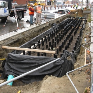
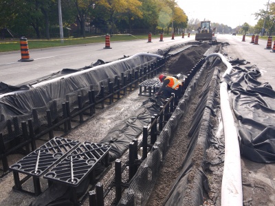
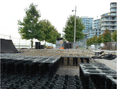
Soil cells under construction.
Soil cell installation on Central Parkway in Mississauga.
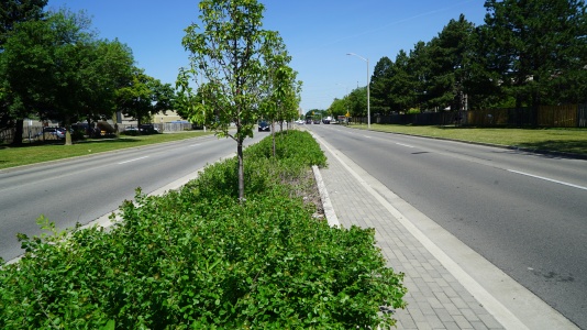
Built in 2014, this stormwater planter on Central Parkway in Mississauga uses supported soil cells and is functioning well.
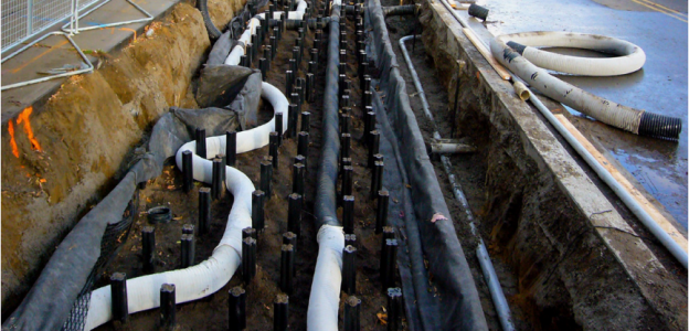
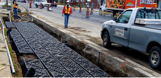
Soil Cell installation along the Moynes and Berl Avenues on north side of The Queensway in Toronto. The picture depicts stormwater distribution pipes through the system, used to help provide water to the trees that will be later planted in the BMP feature.
Photo credit: City of Toronto
Silva Cell “top” deck prior to organic layer and screenings for pavers. Photo credit: City of Toronto
Soil Cells being installed along Edgewater Drive for Waterfront Toronto.
Photo credit: DeepRoot
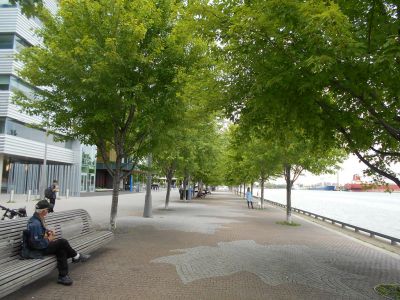
Stormwater Tree Trenches at East Bayfront Promenade, Toronto.
Photo credit: DeepRoot
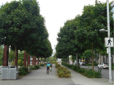
Seawall Soil Cells (Tree Trenches) located in Vancouver.
Photo credit:City of Vancouver
Stormwater tree trenches designed with a structural concrete pad over top of the installation.
Photo credit:DeepRoot


References[edit]
Also see references as direct web page links above.
- ↑ Crow, P. (2005). The Influence of Soils and Species on Tree Root Depth. Edinburgh. Retrieved from https://www.forestry.gov.uk/pdf/FCIN078.pdf/$FILE/FCIN078.pdf
- ↑ Wilkus A., 'Slope Style', Landscape Architecture Magazine, April 2018, accessed 21 December 2018, https://landscapearchitecturemagazine.org/2018/04/24/slope-style/
- ↑ City of Toronto. 2020. Construction Specifications and Drawings for Sewers and Watermains. https://www.toronto.ca/services-payments/building-construction/infrastructure-city-construction/construction-standards-permits/standards-for-designing-and-constructing-city-infrastructure/construction-specifications-for-sewers-and-watermains/
- ↑ City of Toronto. 2020. Construction Specifications and Drawings for Sewers and Watermains. https://www.toronto.ca/services-payments/building-construction/infrastructure-city-construction/construction-standards-permits/standards-for-designing-and-constructing-city-infrastructure/construction-specifications-for-sewers-and-watermains/
- ↑ Berland, A., Shiflett, S.A., Shuster, W.D., Garmestani, A.S., Goddard, H.C., Herrmann, D.L. and Hopton, M.E. 2017. The role of trees in urban stormwater management. Landscape and urban planning, 162, pp.167-177. https://pdf.sciencedirectassets.com/271853/1-s2.0-S0169204617X00030/1-s2.0-S0169204617300464/Adam_Berland_green_infrastructure_2017.pdf
- ↑ Kuehler, E., Hathaway, J. and Tirpak, A. 2017. Quantifying the benefits of urban forest systems as a component of the green infrastructure stormwater treatment network. Ecohydrology, 10(3), p.e1813. https://www.srs.fs.usda.gov/pubs/ja/2017/ja_2017_kuehler_001.pdf
- ↑ Urban, J. 2008. Up By Roots: Healthy soils and trees in the built environment. International Society of Arboriculture. http://www.jamesurban.net/up-by-roots#:~:text=Up%20By%20Roots%2C%20written%20by,trees%20in%20the%20built%20environment.
- ↑ Urban, J. 2014. Urban Soil and Site Assessment [Presentation]. University of Washington Botanic Gardens. Seattle, WA https://botanicgardens.uw.edu/wp-content/uploads/sites/7/2014/10/Urban_Soils_Jim_Urban.pdf.
- ↑ Page, J.L., Winston, R.J., Hunt, W.F. 2015. Soils beneath suspended pavements: An opportunity for stormwater control and treatment. Ecological Engineering. v.82. pp.40-48. https://www.sciencedirect.com/science/article/abs/pii/S0925857415001706
- ↑ STEP. 2018. The Queensway Sustainable Sidewalk Project https://sustainabletechnologies.ca/app/uploads/2018/10/Queensway-Case-Study_FINAL.pdf
- ↑ STEP. 2020. Assessing the Health of Toronto Street Trees Irrigated by Stormwater. https://sustainabletechnologies.ca/app/uploads/2020/09/Soil-cells-tech-brief-FINAL.pdf
- ↑ Li, J., Alinaghaian, S., Joksimovic, D., Chen, L. An Integrated Hydraulic and Hydrologic Modeling Approach for Roadside Bio-Retention Facilities. Water. 2020, 12, 1248 https://www.mdpi.com/2073-4441/12/5/1248
- ↑ Credit Valley Conservation. 2016. Central Parkway: Road Right-of-Way Retrofits - Case Study. https://cvc.ca/wp-content/uploads/2016/06/CaseStudy_CPW_Final.pdf
- ↑ Credit Valley Conservation. 2016. Central Parkway: Low Impact Development Infrastructure Performance and Risk Assessment - Technical Report. https://cvc.ca/wp-content/uploads//2021/07/TechReport_CPW_Final.pdf
- ↑ Gao, J., Pan, J., Hu, N. and Xie, C., 2018. Hydrologic performance of bioretention in an expressway service area. Water Science and Technology, 77(7), pp.1829-1837.
- ↑ Dietz, M.E. and J.C. Clausen. 2005. A field evaluation of rain garden flow and pollutant treatment. Water Air and Soil Pollution. Vol. 167. No. 2. pp. 201-208. http://citeseerx.ist.psu.edu/viewdoc/download?doi=10.1.1.365.9417&rep=rep1&type=pdf
- ↑ Ermilio, J.F., 2005. Characterization study of a bio-infiltration stormwater BMP (Doctoral dissertation, Villanova University). https://www1.villanova.edu/content/dam/villanova/engineering/vcase/vusp/Ermilio-Thesis06.pdf
- ↑ Emerson, C., Traver, R. 2004. The Villanova Bio-infiltration Traffic Island: Project Overview. Proceedings of 2004 World Water and Environmental Resources Congress (EWRI/ASCE). Salt Lake City, Utah, June 22 – July 1, 2004. https://ascelibrary.org/doi/book/10.1061/9780784407370
- ↑ Mahmoud, A., Alam, T., Rahman, M.Y.A., Sanchez, A., Guerrero, J. and Jones, K.D. 2019. Evaluation of field-scale stormwater bioretention structure flow and pollutant load reductions in a semi-arid coastal climate. Ecological Engineering, 142, p.100007. https://www.sciencedirect.com/science/article/pii/S2590290319300070
- ↑ Gao, J., Pan, J., Hu, N. and Xie, C., 2018. Hydrologic performance of bioretention in an expressway service area. Water Science and Technology, 77(7), pp.1829-1837.
- ↑ Winston, R.J., Dorsey, J.D. and Hunt, W.F. 2016. Quantifying volume reduction and peak flow mitigation for three bioretention cells in clay soils in northeast Ohio. Science of the Total Environment, 553, pp.83-95.
- ↑ DeBusk, K.M. and Wynn, T.M., 2011. Storm-water bioretention for runoff quality and quantity mitigation. Journal of Environmental Engineering, 137(9), pp.800-808. https://www.webpages.uidaho.edu/ce431/Articles/DeBusk-ASCE-2011.pdf
- ↑ Li, H., Sharkey, L.J., Hunt, W.F., and Davis, A.P. 2009. Mitigation of Impervious Surface Hydrology Using Bioretention in North Carolina and Maryland. Journal of Hydrologic Engineering. Vol. 14. No. 4. pp. 407-415.
- ↑ Smith, R and W. Hunt. 2007. Pollutant removals in bioretention cells with grass cover. Proceedings 2nd National Low Impact Development Conference. Wilmington, NC. March 13-15, 2007.
- ↑ Hunt, W.F. and Lord, W.G. 2006. Bioretention Performance, Design, Construction, and Maintenance. North Carolina Cooperative Extension Service Bulletin. Urban Waterways Series. AG-588-5. North Carolina State University. Raleigh, NC.
- ↑ STEP. 2019. Comparative Performance Assessment of Bioretention in Ontari0. Technical Brief. https://sustainabletechnologies.ca/app/uploads/2019/10/STEP_Bioretention-Synthesis_Tech-Brief-New-Template-2019-Oct-10.-2019.pdf.
- ↑ Lucke, T., & Nichols, P. W. B. 2015. The pollution removal and stormwater reduction performance of street-side bioretention basins after ten years in operation. Science of The Total Environment, 536, 784-792. doi:http://dx.doi.org/10.1016/j.scitotenv.2015.07.142
- ↑ Hatt, B. E., Fletcher, T. D., & Deletic, A. 2009. Hydrologic and pollutant removal performance of stormwater biofiltration systems at the field scale. Journal of Hydrology, 365(3), 310-321. doi:http://dx.doi.org/10.1016/j.jhydrol.2008.12.001
- ↑ Davis, A.P. 2008. Field performance of bioretention: Hydrology impacts. Journal of hydrologic engineering, 13(2), pp.90-95. https://ascelibrary.org/doi/abs/10.1061/(ASCE)1084-0699(2008)13:2(90)
- ↑ Berland, A., Shiflett, S.A., Shuster, W.D., Garmestani, A.S., Goddard, H.C., Herrmann, D.L., Hopton, M.E. The role of trees in urban stormwater management. Landscape and Urban Planning. v.162. pp.167-177. https://www.sciencedirect.com/science/article/abs/pii/S0169204617300464?via%3Dihub
- ↑ Xiao, Q., McPherson, E.G.. 2016. Surface water storage capacity of twenty tree species in Davis, California. Journal of Environmental Quality. v.45. pp. 188-198. https://acsess.onlinelibrary.wiley.com/doi/abs/10.2134/jeq2015.02.0092
- ↑ Scharenbroch, B.C., Morgenroth, J., Maule, B. 2016. Tree species suitability to bioswales and impact on the urban water budget. Journal of Environmental Quality. v.45. pp. 199-206. https://acsess.onlinelibrary.wiley.com/doi/abs/10.2134/jeq2015.01.0060
- ↑ Selbig, W.R., Loheide II, S.P., Shuster, W., Scharenbroch, B.C., Coville, R.C., Kruegler, J., Avery, W., Haefner, R., Nowak, D. Quantifying stormwater runoff volume reduction benefit of urban street tree canopy. Science of the Total Environment. v.806 (2022) 151296. https://www.sciencedirect.com/science/article/abs/pii/S0048969721063749?via%3Dihub
- ↑ Vega, O.M. Green infrastructure in the City of Vancouver: performance monitoring of stormwater tree trenches and bioswales. UBC Theses and Dissertations. https://open.library.ubc.ca/soa/cIRcle/collections/ubctheses/24/items/1.0378388
- ↑ Elliott, R.M., Adkins, E.R., Culligan, P.J, Palmer, M.I., Stormwater infiltration capacity of street tree pits: Quantifying the influence of different design and management strategies in New York City. Ecological Engineering. v.111. pp. 157-166. https://www.sciencedirect.com/science/article/abs/pii/S0925857417306365
- ↑ Grey, V., Livesley, S.J., Fletcher, T.D. and Szota, C. 2018. Tree pits to help mitigate runoff in dense urban areas. Journal of Hydrology, 565, pp.400-410. https://www.sciencedirect.com/science/article/abs/pii/S0022169418306346?via%3Dihub
- ↑ Tirpak, R.A., Hathaway, J.M., Franklin, J.A. and Khojandi, A. 2018. The health of trees in bioretention: A survey and analysis of influential variables. Journal of Sustainable Water in the Built Environment, 4(4), p.04018011. https://ascelibrary.org/doi/10.1061/JSWBAY.0000865
- ↑ Kuehler, E., Hathaway, J. and Tirpak, A. 2017. Quantifying the benefits of urban forest systems as a component of the green infrastructure stormwater treatment network. Ecohydrology, 10(3), p.e1813. https://www.srs.fs.usda.gov/pubs/ja/2017/ja_2017_kuehler_001.pdf
- ↑ Li, S., Dai, L., Wang, H., Wang, Y., He, Z., & Lin, S. (2017). Estimating leaf area density of individual trees using the point cloud segmentation of terrestrial LiDAR data and a voxel-based model. Remote sensing, 9(11), 1202. https://www.mdpi.com/2072-4292/9/11/1202/pdf
- ↑ Huang, J.Y., Black, T.A., Jassal, R.S. and Lavkulich, L.L. 2017. Modelling rainfall interception by urban trees. Canadian Water Resources Journal/Revue canadienne des ressources hydriques, 42(4), pp.336-348. https://www.researchgate.net/profile/LesLavkulich/publication/320085997_Modelling_rainfall_interception_by_urban_trees/links/59fc87bf0f7e9b9968bdc715/Modelling-rainfall-interception-by-urban-trees.pdf
- ↑ Abuelgasim, A. A., & Leblanc, S. G. (2011). Leaf area index mapping in northern Canada. International journal of remote sensing, 32(18), 5059-5076. https://www.academia.edu/download/55035075/Leaf_area_index_mapping_in_northern_Canada.pdf
- ↑ Washington Stormwater Center. 2022. Tree Project. https://www.wastormwatercenter.org/project/tree-project/