Difference between revisions of "Stormwater Thermal Mitigation"
Dean Young (talk | contribs) |
Dean Young (talk | contribs) |
||
| Line 7: | Line 7: | ||
==Thermal Load== | ==Thermal Load== | ||
{{float right|{{#widget:YouTube|id=KaGMrWluA9Y}}}} | {{float right|{{#widget:YouTube|id=KaGMrWluA9Y}}}} | ||
| − | Since stream warming is influenced by the runoff temperature and volume of runoff draining to streams, impacts are best assessed through an evaluation of thermal loads both in the stream and in runoff discharged to streams. The thermal load is a function of the flow rate, water temperature, water density and heat capacity of water (or the energy required to increase a kg of water by 1 degree | + | Since stream warming is influenced by the runoff temperature and volume of runoff draining to streams, impacts are best assessed through an evaluation of thermal loads both in the stream and in runoff discharged to streams. The thermal load is a function of the flow rate, water temperature, water density and heat capacity of water (or the energy required to increase a kg of water by 1 degree Celsius). |
'''''Thermal Load = Q x ρ x T x C''''' | '''''Thermal Load = Q x ρ x T x C''''' | ||
Revision as of 22:10, 3 April 2023

Overview[edit]
Streams draining urban areas are often much warmer than those draining natural ones due to changes in surface cover and hydrology. Urbanization increases stream temperatures by decreasing riparian shading and replacing natural landscapes with hard, dark-coloured pavements and roofs that absorb and store heat from the sun. The added impervious cover increases the volume of heated runoff while at the same time reducing discharge of cool groundwater to streams. This heating effect is further exacerbated as runoff flows through stormwater management ponds or other impoundments, where detained water is exposed to solar warming for extended time periods between rain events. This page explores different techniques for mitigating the effects of urbanization on the stream thermal regime.[2]
Thermal Load[edit]
Since stream warming is influenced by the runoff temperature and volume of runoff draining to streams, impacts are best assessed through an evaluation of thermal loads both in the stream and in runoff discharged to streams. The thermal load is a function of the flow rate, water temperature, water density and heat capacity of water (or the energy required to increase a kg of water by 1 degree Celsius).
Thermal Load = Q x ρ x T x C
Where:
- Q = flow rate (m3/s)
- ρ = water density (1000kg/m3)
- T = water temperature (°C)
- C = heat capacity of water (4187J/kg°C)
Since urban runoff volumes often increase by 2 to 5 times after development, and stormwater pond effluent temperatures are between 4 and 11°C warmer than pond influent temperatures in the summer, the overall thermal load increases to streams can be very significant (Van Seters and Dougherty, 2019).[3]
Selecting a Stream Temperature Target[edit]
Setting a stream temperature threshold for the protection of aquatic life can be based on:
- Matching the water temperature regime of either a known pre-development thermal condition or the thermal condition of a nearby undisturbed stream with similar characteristics; or,
- Meeting the upper tolerance of one or more target aquatic species.
Thermal Mitigation Techniques[edit]
Techniques for mitigating thermal impacts to streams can be implemented:
- Within the catchment near the source of runoff,
- Along the conveyance route to a treatment facility
- Within the stormwater pond or other stormwater treatment facility; and/or,
- Within the stream corridor.
Upstream of the Pond[edit]
Any measure that decreases runoff volumes or temperatures or both can help mitigate thermal loads to streams or downstream treatment facilities. Examples include bioretention, infiltration trenches or chambers, enhanced swales, permeable pavements, absorbent landscaping and increased canopy cover. The figures below show the temperature (event mean temperature) and thermal load reduction results from several LID practices monitored in the Greater Toronto Area (Van Seters and Dougherty, 2019).[3] The most effective practices were deeper systems such as trenches, some deep bioretention facilities, and practices that promote significant runoff volume reductions. Beyond reducing temperatures and runoff volumes, enhancing infiltration also helps re-establish the natural baseflow regime that existed prior to development.


Within the Pond Block[edit]

There are several opportunities to mitigate thermal impacts both within the pond itself and/or implemented within the upstream drainage area (and the lands surrounding) of the pond. Options shown in past studies to provide appreciable thermal mitigation benefits include (Van Seters and Dougherty, 2019)[3].
Subsurface Draw Outlets[edit]
A reverse sloped outlet pipe drains cooler water from below the pond surface to a control manhole that is accessible from the bank for ease of maintenance. Deeper outlet result in cooler outflows than shallow outlets because pond water temperatures decrease with depth. The figure below shows an example of thermal stratification during the summer in a deep pond using said subsurface outlets.
Design Considerations
- Subsurface outlet inverts should be a minimum 1.2 m below the permanent pool water level to avoid influence from solar induced diurnal fluctuations.
- Subsurface outlets need to elevated from the pond bottom by between 1 and 1.5 m to allow space for sediment to accumulate. Reducing the separation distance may mean that the pond will need to be cleaned prior to its normal life cycle maintenance schedule, as per MECP guidance (link to our stormwater inspection and maintenance guide).
- Meeting outlet to bottom separation requirements by over excavating around the reverse slope outlet pipe will not provide the same temperature reduction benefits as a uniformly deep pond because the scour pool promotes vertical mixing of warmer top water with bottom water and there will be less cool bottom water below the outlet invert.
- Deeper ponds may require larger footprints to meet the MECP side slope requirements of 5:1 above the permanent pool and 3:1 elsewhere.
- Reverse sloped pipes should not be solid (not perforated) to ensure water is drawn from the deeper part of the pond.

Expected Performance
- Relative to a surface draw outlet, the expected 95th percentile temperature reduction provided by a 2 m deep draw outlet for years with similar air temperatures is between 3 and 5⁰C.
- Water drained from outlets 2m below the surface will typically be less than 24°C at least 95% of the time.
Night Time Release Outlets[edit]
Employs real time control on pond outlets to automatically close outlets during the day when surface outflow from ponds is warmer, and release water during the night when outflow temperatures are cooler. The outlets are configured and programmed to maintain release rates below threshold values for stream erosion prevention and match pre-development peak flow rates.

Design Considerations
- Optimal 8 hour duration for night time release outlets was found to be between 3 AM and 10 AM inclusive based on data from 4 ponds
- Optimal 4 hour duration release times were found to be between 6 and 9 AM inclusive (Van Seters and Dougherty, 2019)[3].
- Robust automation technology is critical to avoid excessive repairs and down time.
- Electrical supply and back-up power are typically needed at the outlet to reduce operation and maintenance requirements
Expected Performance
- Based on modelling of four ponds, the 95th percentile temperature reduction for ponds with night time release outlets was calculated to be approximately 1.6⁰C for surface draw outlets, and 0.6⁰C for an outlet 1.4 m below the permanent pool level. For deeper outlets, the benefits of night time release are very small as temperatures from these outlets do not exhibit strong diurnal variations.
Cooling Trenches[edit]
Cooling trenches typically consist of one or more geotextile wrapped perforated pipes embedded in a clear stone filled trench that is buried underground. Water temperatures are reduced through heat transfer from the water passing through the trench to the stone and surrounding soils. Cooling trenches may be installed downstream of the primary pond outlet or draw from a secondary orifice controlled outlet draining water from the pond at or below the permanent pool water level (e.g Van Seters and Graham, 2013[6].; TRCA, 2020[7]). Further information about these innovative cooling trench features installed as part of the stormwater pond operation design in two sites located in Markham, ON. visit the STEP project page. The permanent pool of stormwater management ponds acts as a heat sink during the summer, resulting in warmer summer discharges during both storm and baseflow conditions.
The technology, known as the Groundwater Emulation Management System (GEMS), was designed to maintain cool stream discharge from the SWM pond catchment at a level similar to that experienced prior to development. This is accomplished by draining water at a controlled rate from the permanent pool of a stormwater pond to a cooling/infiltration trench. The cooling trench lowers the temperature of pond water through below ground heat transfer and discharges to the receiving watercourse at a rate and volume mimicking the natural discharge of groundwater. Estimated reductions in groundwater recharge caused by the conversion of land from agriculture and open space to residential use provided the basis for setting continuous flow rates released into the system.

Design Considerations
- Built-in overflows bypass high flows to help enhance thermal function and prevent excessive sediment build-up in the trench.
- Available research shows that the trench storage volume should be equal to or greater than 5% of the runoff volume discharged from the pond during the 25 mm event. Trenches with smaller storage volumes cannot be relied on to provide any cooling benefits, although under favourable conditions, these may still provide some cooling.
- Flush-out pipes, high flow bypasses and sediment pre-treatment mechanisms should be provided to reduce maintenance.
- Pre-treatment filters, energy dissipators or isolator rows are useful to improve overall functionality but will require regular inspection and maintenance to ensure they are fulfilling their intended function.
- Secondary pond outlets that drain water from 0.5 m below the permanent pool elevation to cooling trenches can help to reduce or eliminate the long duration and very warm interevent flows.
- Trenches may incorporate an infiltration function to help further reduce thermal loads if native soils and groundwater levels are suitable.
Expected Performance
- Performance of primary outlet cooling trenches is highly variable due to differences in cooling trench sizing, design, initial water temperature and degree of groundwater interaction
- Based on case studies reviewed, primary outlet trenches without groundwater interaction may provide summer temperature cooling of the warmest flows by roughly 1 to 3⁰C if the trench storage volume is equal to or greater than 5% of the runoff volume discharged from the pond during the 25 mm event.

Infiltration Systems[edit]
Infiltration systems may be used as an alternative to cooling trenches for mitigating the thermal effects of pond outflows in areas not constrained by water tables and space. As with cooling trenches, these may be installed on the main pond outlet or a secondary outlet. Since water tables at the pond outlet are often high, large void chambers may be more suitable than trenches as they provide greater storage per unit depth.
The volumes infiltrated may also be used to meet site water balance requirements. Proponents will need to consult with local approval agencies to determine whether the typical 1 meter separation depth to groundwater may be waived given that the infiltrated water has been treated through the pond.
Analysis of temperature and thermal load data from three monitored ponds showed that the bottom area of the infiltration area would need to be up to 7% that of the pond area depending on the infiltration capacity of the native soils. These areas could be reduced by 40% if the outlet draws water from 0.25 m below the surface, and further reduced for deeper outlets (Van Seters and Dougherty, 2019)[3].
3 mm/h |
12mm/h |
25mm/h | |
|---|---|---|---|
| Pond A |
4.0% | 1.0% | 0.5% |
| Pond B |
4.7% | 1.2% | 0.6% |
| Pond C |
6.6% | 1.6% | 0.8% |
| Note: Infiltration system footprint needed to provide pond outflow thermal load reduction benefits equivalent to a 2m bottom draw outlet (expressed as a percent of pond area). | |||
Geothermal Cooling[edit]
This innovative approach uses one or more deep (180 m) geothermal boreholes connected in a closed loop with a pond heat exchanger to cool outflows from stormwater ponds. A metal or polyethylene heat exchanger is installed in an enclosure at the outlet of the pond. A heat transfer fluid is pumped through the closed loop to maximize transfer of heat energy from the warm water to the much colder ground. Warm outflows from the pond enter the enclosure and pass over the pond heat exchanger, which transfers energy from the water to the closed loop and into the ground. The approach was piloted by TRCA/STEP, in partnership with the City of Brampton, on a small pond in Brampton (Janssen and Van Seters, 2021[8] and 2022[1])
As part of the initiative an online sizing tool for geothermal systems was developed - you can view it by click the button below:


Design Considerations
- Heat exchangers come in different sizes and are made of different materials. Metal heat exchangers (typically stainless steel) are more efficient than polyethylene and take up much less space.
- Antifreeze solutions are needed in the hydronic circuit because a portion of the closed loop is above ground and would freeze over the winter. Non-toxic heat transfer fluids include propylene glycol/water and ethanol. The latter has better heat transfer properties and takes less energy to pump.
- The enclosure can be bottomless if the soils and groundwater table is suitable for rapid infiltration.
- Borehole field and heat exchanger sizing should be done based on the estimated (modelled) or, preferably, monitored thermal load, with a target of achieving 95% of the desired temperature threshold recognizing that it is not feasible to cool large flows. Elevated outflow temperatures occur most frequently during low flows (i.e. dry weather flows).
- The pump used to circulate the heat transfer fluid through the ground loop may be powered by an electrical connection or solar panels. Larger systems may need designated electrical connections.
- Initial investigations suggest that systems can be sized based on the average pond outflow rate over a given year to achieve defined temperature thresholds most of the time.
Expected Performance
Geothermal Cooling works best with subsurface draw outlets (1.2 m or deeper) that provide cooling of the higher flows and would be less expensive than installing additional boreholes (at least in new builds). When sized appropriately, geothermal systems can shave a few degrees off of the average pond outflow temperature.

See above an example of a geothermal system configuration showing the surface heat exchanger (SHX) in the vault and the borehole ground heat exchanger (GHX). An inexpensive pump circulates heat transfer fluid through the closed loop continuously.
Other Options[edit]
Vegetated channels installed downstream of pond outlets can help to reduce temperatures through shading, although typically a long channel is needed to have an appreciable benefit on temperatures.
Underground detention chambers, have the potential to cool inflowing runoff and maintain temperatures suitable for discharge to cool water fisheries (Drake et al, 2015)[9]
Surface cover also has the potential to provide cooling benefits. Options include floating islands, solar panels, shade balls, trellis infrastructure to support vines and south shading of east west oriented ponds with trees. The data from various studies shows that surface cover needs to cover more than 70% of the pond with an opaque surface material to promote appreciable temperature reduction benefits. Trees on the banks of ponds will not provide immediate thermal benefits as they will take time to grow, but are otherwise an excellent long term strategy.
Ponds with large length to width ratios, oriented east-west with shading on the south side can also provide shading, although it will take several years for the shade to become established.
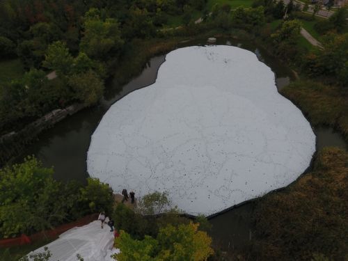
An example of an alternative option for thermal mitigation - White shade balls. These specialized balls were used to cover this pond as part of a thermal mitigation pilot project in the City of Brampton. Photo Source: TRCA, 2020. To read more about this novel option for thermal mitigation, click here: Shade Balls study[10]
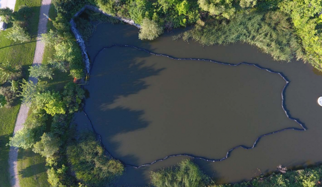
An aerial view of the barrier system in place before shade balls were deployed in Esker Pond. To read more click here: Shade Balls study[10]
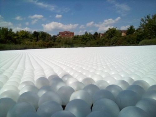
A close up of white shade balls used in Esker Pond as part of a thermal mitigation pilot. An example of an alternative option for thermal mitigation. To read more click here: Shade Balls study[10]


In the Stream Corridor[edit]
Riparian plantings are the primary means of preserving or reducing thermal enrichment of streams.
These strategies work best for small streams with high vegetation or trees that provide significant reductions in light intensity. Studies have shown that streams with extensive riparian shading have maximum summer temperatures between 1 or 2 degrees lower than unshaded streams (AECOM, 2009[11]; Dugdale et al., 2018[12]).
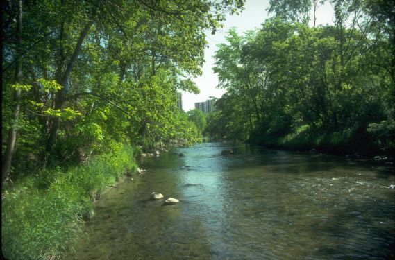
A stream with mature Riparian vegetation surrounding it to help reduce thermal enrichment. Photo Source: TRCA
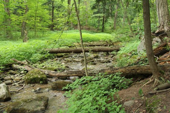
Another example of a stream with mature riparian vegetation in Glen Haffy Conservation Area from July, 2012 Photo Source: TRCA
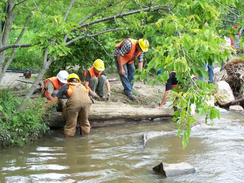
Greenwood stream restoration taking place by TRCA staff to improve habitat for native plants, fish and wildlife and maintain connectivity to other important ecoregions within the Duffins Creek watershed. Photo Source: TRCA


References[edit]
- ↑ 1.0 1.1 Janssen, E. and Van Seters, T. 2022. Thermal Mitigation of Stormwater Management Pond Outflows Using Geothermal Cooling. Journal of Water Management Modeling. https://www.chijournal.org/Content/Files/C483.pdf
- ↑ Credit Valley Conservation. 2011. Thermal Impacts of Urbanization including Preventative and Mitigation Techniques. Prepared by AECOM under contract to CVC, Mississauga, Ontario. https://cvc.ca/wp-content/uploads/2011/01/cvc-thermal-impacts-urbanization.pdf
- ↑ 3.0 3.1 3.2 3.3 3.4 3.5 3.6 3.7 3.8 Van Seters, T., and Dougherty, J. 2019. Data Synthesis and Design Considerations for Stormwater Thermal Mitigation Measures. Sustainable Technologies Evaluation Program. Ontario. https://sustainabletechnologies.ca/app/uploads/2019/04/Thermal-Synthesis-Final.pdf
- ↑ TRCA. 2017. Furthering the State of Knowledge on Stormwater Management - News. October 4th, 2017. Accessed: April 18th, 2022. https://trca.ca/news/furthering-the-state-of-knowledge-on-stormwater-management/
- ↑ Ministry of the Environment. 2003. Stormwater Management Planning and Design Manual. March, 2003. ISBN 0-7794-2969-9. PIBS 4329e. https://dr6j45jk9xcmk.cloudfront.net/documents/1757/195-stormwater-planning-and-design-en.pdf
- ↑ 6.0 6.1 Van Seters, T., Graham, C. 2013. Evaluation of an Innovative Technique for Augmenting Stream Baseflows and Mitigating the Thermal Impacts of Stormwater Ponds. Sustainable Technologies Evaluation Program, Toronto and Region Conservation Authority, Toronto, Ontario. https://sustainabletechnologies.ca/app/uploads/2013/08/Cooling-trench-final-2013a.pdf
- ↑ Toronto and Region Conservation Authority (TRCA) 2020. Evaluation of a Thermal Mitigation System on the Heritage at Victoria Square Pond in Markham. Toronto and Region Conservation Authority, Vaughan, Ontario. https://sustainabletechnologies.ca/app/uploads/2021/01/TM-Heritage-report-2021R.pdf
- ↑ Janssen, E., Van Seters, T. 2021. Geothermal-based Thermal Mitigation of Stormwater Retention Pond Outflows: Report Addendum. Sustainable Technologies Evaluation Program, Toronto and Region Conservation Authority, Vaughan, Ontario. https://sustainabletechnologies.ca/app/uploads/2022/03/Geo_Cooling_Report_2021.pdf
- ↑ McIntosh, N., Drake, J., Young, D. and Spencer, J. 2015. Modeling Sedimentation in Underground Stormwater Detention Chamber Systems. In International Low Impact Development Conference 2015: LID: It Works in All Climates and Soils (pp. 43-52). https://sustainabletechnologies.ca/home/urban-runoff-green-infrastructure/low-impact-development/soakaways-infiltration-trenches-and-chambers/evaluation-of-an-underground-stormwater-detention-chamber-system-in-markham-ontario/
- ↑ 10.0 10.1 10.2 Rocha, L., and VanSeters, T.2020. Evaluation of shade balls for mitigating summer heating of stormwater management ponds. Toronto and Region Conservation Authority, Vaughan, Ontario. https://sustainabletechnologies.ca/home/urban-runoff-green-infrastructure/thermal-mitigation/evaluation-shade-balls-mitigating-summer-heating-stormwater-management-ponds/
- ↑ AECOM Canada Ltd. 2009. Hanlon Creek Business Park stream temperature impact report, continuous modelling with HSP-F. A report to the City of Guelph. https://guelph.ca/wp-content/uploads/HCBP_EIR_Report.pdf
- ↑ Dugdale, S.J., Malcolm, I.A., Kantola, K. and Hannah, D.M. 2018. Stream temperature under contrasting riparian forest cover: Understanding thermal dynamics and heat exchange processes. Science of the Total Environment, 610, pp.1375-1389. https://www.sciencedirect.com/science/article/pii/S0048969717321952