Pretreatment features

Forebays are a form of pretreatment for open inlets such as curb cuts. Energy of the incoming flow is dissipated, causing suspended particles to drop out of the water. These accumulated particles/sediment can then be easily swept or vacuumed during routine maintenance and doesn't end up clogging downstream filter media or material. A well designed forebay will distribute the flow, reducing erosion around the inlet. One effective way of achieving this is by surrounding the pad with some form of level spreader on all sides. The level spreading could be a sharp crested weir in metal or concrete, or be soft edged with irregular landscaping stone.
Design[edit]
1. The required volume for a small forebay, serving up to 2 Ha (Vf, m³), may be calculated as:

Where:
- Ac = The area of the catchment (m²),
- R = The capture efficiency (default to 0.8),
- Lo = The sediment loading rate (m³/Ha/yr), and
- Fc = The cleanout frequency (yrs)
Sediment loading rates from impervious surfaces studied by STEP were between 0.3 - 0.6 m³/ha/yr [1]. In Brisbane a value of 0.6 m³/ha/yr is the default value used to size small forebays [2].
2. a) The area of a forebay with (Af) 80 % capture efficiency of particles ≥ 1 mm may be estimated[2] as:

Where:
- Q = Design flow rate (m³/s), and
2. b) To size a forebay for a maximum depth (df, m), where df must ≤0.3 m and between 0.1 - 0.2 m is recommended:

It is recommended that both sizing calculations be made and the forebay be designed to meet both targets. In some cases the additional storage required to meet both targets will reduce the expected frequency of maintenance. See below.
Example calculation[edit]
A parking lot catchment of 1.7 Ha is being routed through a small forebay into a bioretention cell. The design flow rate is 0.02 m³/s. The system should be designed to require cleaning no more often than once per year. The volume is calculated as:

The area required to keep the maximum head of water within the forebay to 0.15 m is calculated as:

The area required to settle the 1 mm particles is calculated as:

So to meet the target particle removal, the forebay will be 12 m² in area. This gives the storage volume of 1.2 m³, which can be returned to the initial equation to determine the cleaning frequency as:

Gallery[edit]
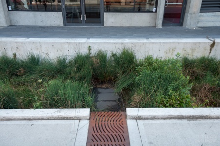
Solid splash pad preventing erosion from the flow from the inlet. Image credit Dylan Passmore
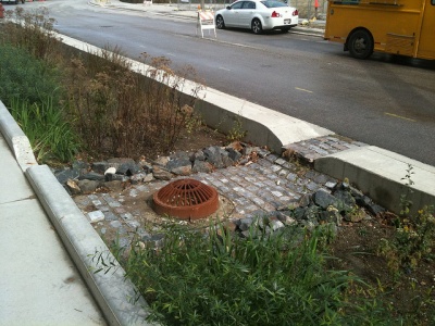
Forebay connected to drainage area in the roadway with a curb cut, overflow visible in the centre of the feature, level spreading is encouraged with the rock check dams, Milwaukee, WI, Photo credit: Aaron Volkening
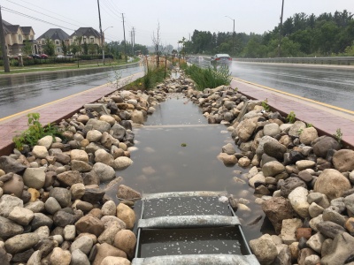
Rounded 'river rock' and a series of check dams slow water from this inlet.
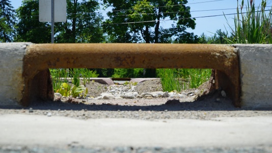
This forebay has a rock splash pad to slow water down before it reaches a bioswale.
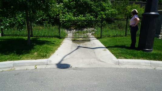
Incoming water from these curb cuts is slowed by river rock splash pads.


- ↑ Goncalves, C., & Van Seters, T. (2012). Characterization of Particle Size Distributions of Runoff from High Impervious Urban Catchments in the Greater Toronto Area. Retrieved from https://sustainabletechnologies.ca/app/uploads/2013/03/PSD-2012-final.pdf
- ↑ 2.0 2.1 Healthy Waterways Ltd. (2014). Bioretention Technical Design Guidelines. Retrieved from https://hlw.org.au/u/lib/mob/20150715140823_de4e60ebc5526e263/wbd_2014_bioretentiontdg_mq_online.pdf