Permeable paving

Overview[edit]
Permeable paving allows stormwater to drain through the surface and into a stone reservoir, where it infiltrates into the underlying native soil or is temporarily detained.
The following are different types of permeable paving:
- Permeable interlocking concrete pavers (PICP)
- Plastic or concrete grid systems
- Pervious concrete
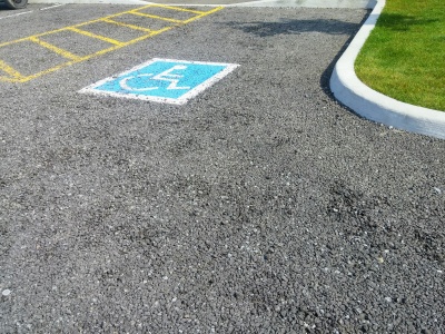
- Pervious asphalt
Permeable paving is ideal for:
- Sites with limited space for other surface stormwater BMPs
- Projects such as low traffic roads, parking lots, driveways, pedestrian plazas and walkways
The fundamental components of a permeable paving system are:
- interlocking blocks with infiltration spaces between
- Precast pervious slabs or pavers
- a cast in place surface without fines, so that the finish is pervious to water
- a bedding course to stabilize the surface
- underground storage layer of aggregate
Additional components may include:
- an underdrain system
Planning considerations[edit]
Permeable pavements are surfaces that encourage infiltration. They can be used in place of conventional asphalt or concrete pavement. These alternatives contain pores, spaces and joints for allowing stormwater to pass through to a stone base, where it infiltrates into underlying native soils or is temporarily detained. Types of permeable pavement include:
- Pervious concrete
- Porous asphalt
- Permeable interlocking concrete pavers (PICP, or just permeable pavers)
Geometry and Site Layout[edit]
Permeable paving can be used for entire parking lot areas or driveways and can be designed to receive runoff from adjacent impervious surfaces. For example, the parking spaces in a parking lot may be permeable pavers while the drive lanes themselves are impervious asphalt. In general, the impervious area should not exceed 1.2 times the area of the permeable paving which receives the runoff. A hybrid permeable paving/infiltration chamber design can feature connection of a roof downspout directly to the stone reservoir of the permeable paving system, which is sized to store runoff from both the pavement surface and the roof drainage area.
Pretreatment[edit]
In most designs, the surface acts as pretreatment to the stone reservoir below. Periodic vacuum sweeping and preventative measures like not storing snow or other materials on the pavement are critical to prevent clogging. Another pretreatment element is to have a choking layer above the coarse gravel storage reservoir.
Landscaping[edit]
Landscaped areas must drain away from permeable paving to prevent sediments from running onto the surface. Urban trees will benefit from being surrounded by permeable paving rather than impervious cover, because their roots receive more air and water. Interlocking pavers used around the base of a tree may be removed as the tree grows.
Risk of Groundwater Contamination[edit]
- Stormwater infiltration practices should not receive runoff from high traffic areas where large amounts of de-icing salts are applied (e.g., busy highways), nor from pollution hot spots (e.g., source areas where land uses or activities have the potential to generate highly contaminated runoff such as vehicle fuelling, servicing or demolition areas, outdoor storage or handling areas for hazardous materials and some heavy industry sites)
- Prioritize infiltration of runoff from source areas that are comparatively less contaminated such as roofs, low traffic roads and parking areas
- Apply sedimentation pretreatment practices (e.g., oil and grit separators) before infiltration of road or parking area runoff
Heavy Vehicle Traffic[edit]
Permeable paving is not typically used in locations subject to heavy loads. However, some permeable pavers are designed for heavy loads and have been used in commercial port loading and storage areas.
Setbacks from Buildings[edit]
Permeable paving should be located downslope from building foundations. If the paving does not receive runoff from other surfaces, no setback is required from building foundations. Otherwise, a minimum setback of 4 m down-gradient from building foundations is recommended.
On Private Property[edit]
If permeable paving systems are installed on private lots, property owners or managers will need education on their routine maintenance needs, understanding the long-term maintenance plan. They may also be subject to a legally binding maintenance agreement. An incentive program, such as a storm sewer user fee based on the area of impervious cover on a property that is directly connected to a storm sewer, could be used to encourage property owners or managers to maintain existing practices.
Design[edit]
Modeling permeable paving in the Treatment Train Tool[edit]
Sizing stone reservoirs[edit]
The stone reservoir must meet both runoff storage and structural support requirements. The bottom of the reservoir should be level so that water infiltrates evenly. If the system is not designed for infiltration, the bottom should slope at 1 - 5% toward the underdrain.
Permeable paving: Sizing and modeling
Gallery[edit]
Porous asphalt, Coultice Park, Whitchurch-Stoufville, ON
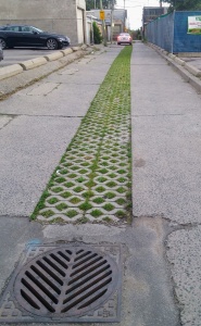
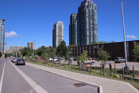
Laneways retrofit program, Toronto ON
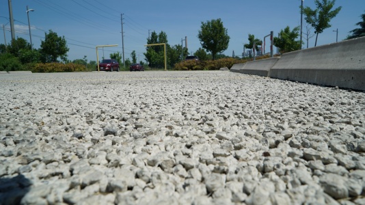
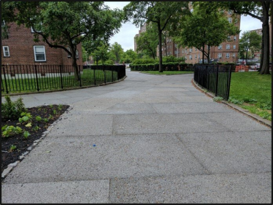
Permeable concrete at Lakeside Park, Mississauga ON
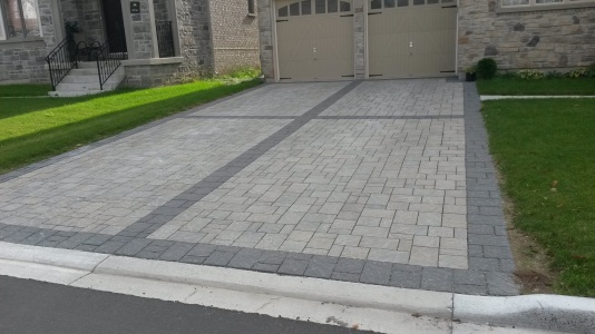
Permeable pavers on residential driveways, Brampton ON
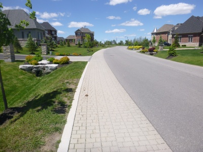
Permeable pavers on a shared street, Georgetown ON
Permeable pavers in parking bays, Mississauga ON (note inspection of bioretention occurring in the background)
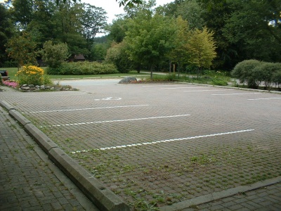
Although this permeable pavement at Belfountain Conservation Area was not maintained, it remains structurally sound after over 30 years of constant use.
Pre-cast pervious concrete slab.
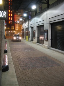
Permeable Interlocking Concrete Pavement (PICP) on a narrow road between buildings in Chicago (Source: ICPI)
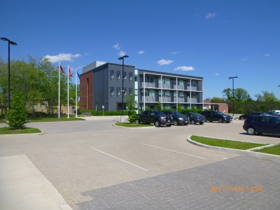
Different colours of permeable pavers in parking lot, CVC headquarters, Mississauga ON
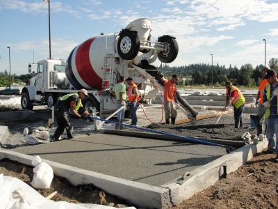
Crews pour pervious concrete into a parking lot (Source: Washington State Dept of Transportation on Flickr)
Inspection wells should be located at the edges or even off the side of permeable pavement areas
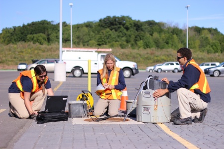
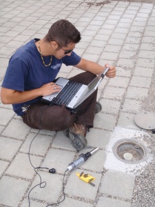
Water quality sampling in permeable pavement study, Mississauga ON
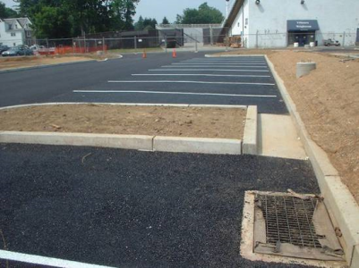
Porous asphalt parking lot (Source: Villanova Urban Stormwater Partnership)
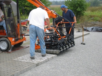
Placement of permeable pavers during construction.


.JPG)


Materials[edit]
Consult the manufacturer for the design specifications of their product. In pervious concrete and porous asphalt systems, the concrete or asphalt mix specifications and construction procedures are key to proper functioning. These systems require well-trained and experienced contractors for installation.
Specifications
Aggregates[edit]

In bioretention systems a choker layer of ≥ 100 mm depth is the recommended method to prevent migration of finer filter media into the underlying storage reservoir aggregate. These same mid-sized granular materials are recommended for use in Stormwater planter underdrains and may be useful in the fine grading of foundations courses for permeable pavements.
Suitable materials include:
- High performance bedding (HPB)
- Clean, angular aggregate screened to between 6 and 10 mm. Widely available and designed specifically for drainage applications. Free from fines by definition.
- HL 6
- Is a clean, angular aggregate screened between 10 and 20 mm. Free from fines by definition.
- Pea Gravel
- Rounded natural aggregate, screened between 5 and 15 mm, and washed free from fines.
In most scenarios, a geotextile layer is unnecessary and has been associated with rapid decline and clogging in some circumstances.
This article gives recommendations for aggregate to be used to store water for infiltration. This is usually called 'clear stone' at aggregate yards.
To see an analysis of Ontario Standard Specifications for granular materials, see OPSS aggregates.
For advice on decorative surface aggregates see Stone
Gravel used for underdrains in bioretention, infiltration trenches and chambers, and exfiltration trenches should be 20 or 50 mm, uniformly-graded, clean (maximum wash loss of 0.5%), crushed angular stone that has a porosity of 0.4[1].
The clean wash to prevent rapid accumulation of fines from the aggregate particles in the base of the reservoir. The uniform grading and the angularity are important to maintain pore throats and clear voids between particles. (i.e. achieve the porosity). Porosity and permeability are directly influenced by the size, gradation and angularity of the particles [2]. See jar test for on-site verification testing protocols.
Gravel with structural requirements should also meet the following criteria:
- Minimum durability index of 35
- Maximum abrasion of 10% for 100 revolutions and maximum of 50% for 500 revolutions
Standard specifications for the gradation of aggregates are maintained by ASTM D2940
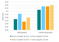
The highest porosity is found in uniformly graded aggregate, as there are no smaller particles to occupy the inter-particle pores. [2]
Higher permeability is found in larger, angular, uniformly graded aggregate. This is due to larger pore sizes and lower tortuosity. [2]


Geotextile[edit]

See Clogging for notes on their application in LID structures.
Geotextiles can be used to prevent downward migration of smaller particles in to larger aggregates, and slump of heavier particles into finer underlying courses. Geotextiles are commonly used on low strength soils (CBR<4). The formation of biofilm on geotextiles has also been shown to improve water quality:
- By degrading petroleum hydrocarbons[3]
- By reducing organic pollutant and nutrient concentrations [4]
- When installing geotextiles an overlap of 150 - 300 mm should be used.
Material specifications should conform to OPSS 1860 for Class II geotextile fabrics [5]. Note when expansive clays are present, a non-infiltrating design may be necessary. If used, geotextile socks around perforated pipes should conform to ASTM D6707 with minimum water flow rate conforming to ASTM D4491 (12,263 L/min/m2 at 5 cm head).
- Fabrics should be woven monofilament or non-woven needle punched.
- Woven slit film and non-woven heat bonded fabrics should not be used, as they are prone to clogging.
In choosing a product, consider:
- The maximum forces that will be exerted on the fabric (i.e., what tensile, tear and puncture strength ratings are required?),
- The load bearing ratio of the underlying native soil (i.e. is the geotextile needed to prevent downward migration of aggregate into the native soil?),
- The texture (i.e., grain size distribution) of the overlying and underlying materials, and
- The suitable apparent opening size (AOS) for non-woven fabrics, or percent open area (POA) for woven fabrics, to maintain water flow even with sediment and microbial film build-up.
| Percent soil/filter media passing 0.075 mm (#200 sieve) | Non-woven fabric apparent opening size (AOS, mm) | Woven fabric percent open area (POA, %) | Permittivity (sec-1) |
|---|---|---|---|
| >85 | ≤ 0.3 | - | 0.1 |
| 50 - 85 | ≤ 0.3 | ≥ 4 | 0.1 |
| 15 - 50 | ≤ 0.6 | ≥ 4 | 0.2 |
| 5 - 15 | ≤ 0.6 | ≥ 4 | 0.5 |
| ≤ 5 | ≤ 0.6 | ≥ 10 | 0.5 |
Performance research[edit]
http://www.mdpi.com/2073-4441/7/4/1595/htm
Landscaping[edit]
Landscaped areas should drain away from permeable paving to prevent sediments from running onto the surface. Urban trees benefit from being surrounded by permeable pavement rather than impervious cover, because their roots receive more air and water, and pavers used around the base of a tree can be removed as the tree grows.
Performance[edit]
|
Starting after TRIECA (end March) members of STEP will be undertaking a literature review on the performance of our most popular BMPs. The results will be combined with the information we have to date from the development of the Treatment Train Tool and agreed performance metrics established. Until then, please feel free to continue to ask questions via email or the feedback box below. |
Permeable pavers can be classified into two categories according to the infiltration rate of the underlying subsoil:
- Full Infiltration: Full infiltration designs are more effective, because little if any of the pollutants generated on the impermeable surfaces leave the site as surface runoff
- Partial Infiltration: Partial infiltration designs with underdrains generate more runoff
Studies in North Carolina have shown the average curve number of permeable pavements to range from a low of 45 to a high of 89. [6]
Partial infiltration designs with underdrains generate more runoff, and as a result, are often used in studies investigating the water quality impact of permeable pavements on surface waters. These studies show load reductions above 50% for total suspended solids, most metals and hydrocarbons [7] [8]
As with all stormwater infiltration practices, risk of groundwater contamination from infiltration of runoff laden with road de-icing salt constituents (typically sodium and chloride) is a significant concern. Chloride ions are extremely mobile in the soil and are readily transported by percolating water to aquifers.
Construction Considerations[edit]
Construction of permeable pavement is a specialized project and should involve experienced contractors. The following general recommendations apply:
- Sediment Control: The treatment area should be fully protected during construction so that no sediment reaches the permeable pavement system and proper erosion and sediment controls must be maintained on site.
- Weather: Porous asphalt and pervious concrete will not properly pour and set in extremely high or low temperatures [9]. One benefit to using permeable pavers is that their installation is not weather dependent.
- Pavement placement: Properly installed permeable pavement requires trained and experienced producers and construction contractors.
Inspection and Maintenance[edit]
Permeable pavements require regular inspection and maintenance to ensure proper functioning. The limiting factor for permeable pavers is clogging within the aggregate layers, filler, or underdrain. Ideally, signs should be posted on the site identifying permeable paver and porous pavement areas. This can also serve as a public awareness and education opportunity. See: Permeable paving: Maintenance
Life cycle costs[edit]
Initial construction costs for permeable pavements are typically higher than conventional asphalt pavement surfaces, largely due to thicker aggregate base needed for stormwater storage. However, the cost difference is reduced or eliminated when total life-cycle costs, or the total cost to construct and maintain the pavement over its lifespan, are considered. Other potential savings and benefits include reduced need for storm sewer pipes and other stormwater practices, less developable land consumed for stormwater treatment, and ancillary benefits (improved aesthetics and reduced urban heat island effect). These systems are especially cost effective in existing urban development where parking lot expansion is needed, but there is not sufficient space for other types of BMPs. They combine parking, stormwater infiltration, retention, and detention into one facility. See also: Cost analysis resources
Proprietary Links[edit]
In our effort to make this guide as functional as possible, we have decided to include proprietary systems and links to manufacturers websites.
Inclusion of such links does not constitute endorsement by the Sustainable Technologies Evaluation Program.
Lists are ordered alphabetically; link updates are welcomed using the form below.
Pre-cast[edit]
- Eco-Optioc, Unilock
- Enviro Pavers, Oaks
- Hydropavers pervious pavers
- Pavedrain, distributed by Nilex
- Terra flo, Santerra
- Stormcrete pervious pavers
Poured in place[edit]
- ↑ Porosity of Structural Backfill, Tech Sheet #1, Stormtech, Nov 2012, http://www.stormtech.com/download_files/pdf/techsheet1.pdf accessed 16 October 2017
- ↑ 2.0 2.1 2.2 Judge, Aaron, "Measurement of the Hydraulic Conductivity of Gravels Using a Laboratory Permeameter and Silty Sands Using Field Testing with Observation Wells" (2013). Dissertations. 746. http://scholarworks.umass.edu/open_access_dissertations/746
- ↑ Newman AP, Coupe SJ, Spicer GE, Lynch D, Robinson K. MAINTENANCE OF OIL-DEGRADING PERMEABLE PAVEMENTS: MICROBES, NUTRIENTS AND LONG-TERM WATER QUALITY PROVISION. https://www.icpi.org/sites/default/files/techpapers/1309.pdf. Accessed July 17, 2017.
- ↑ Paul P, Tota-Maharaj K. Laboratory Studies on Granular Filters and Their Relationship to Geotextiles for Stormwater Pollutant Reduction. Water. 2015;7(4):1595-1609. doi:10.3390/w7041595.
- ↑ ONTARIO PROVINCIAL STANDARD SPECIFICATION METRIC OPSS 1860 MATERIAL SPECIFICATION FOR GEOTEXTILES. 2012. http://www.raqsb.mto.gov.on.ca/techpubs/OPS.nsf/0/2ccb9847eb6c56738525808200628de1/$FILE/OPSS%201860%20Apr12.pdf. Accessed July 17, 2017
- ↑ Bean, E.Z., Hunt, W, F., Bidelspach, D.A. 2007a. Evaluation of Four Permeable Pavement Sites in Eastern North Carolina for Runoff Reduction and Water Quality Impacts. Journal of Irrigation and Drainage Engineering. Vol. 133. No. 6. pp. 583-592.
- ↑ Legret, M and V. Colandani. 1999. Effects of a porous pavement structure with a reservoir structure on runoff water: water quality and fate of metals. Water Science and Technology. 39(2): 111-117
- ↑ Pratt, C.J., Mantle, J.D.G., Schofield, P.A. 1995. UK research into the performance of permeable pavement reservoir structures in controlling stormwater discharge quantity and quality. Water Science Technology. Vol. 32. No. 1. pp. 63-69.
- ↑ City of Portland. 2004. Portland Stormwater Management Manual. Prepared by the Bureau of Environmental Services (BES). Portland, OR.