Overflow

Routing[edit]
- Infiltration facilities can be designed to be inline or offline from the drainage system. See Inlets
- Inline facilities accept all of the flow from a drainage area and convey larger event flows through an overflow outlet. The overflow must be sized to safely convey larger storm events out of the facility.
- The overflow must be situated at the far end of the facility to prevent any localised ponding to cause bypassing of the infiltration facility.
- Offline facilities use flow splitters or bypass channels that only allow the required water quality storage volume to enter the facility.
- Higher flows are diverted and do not enter the infiltration practice. A pipe can by used for this, but a weir or curb cut minimizes clogging and reduces the maintenance frequency.
== The invert of the overflow should be placed at the maximum water surface elevation of the bioretention area. i.e. the maximum ponding depth. A good starting point is around 300 mm over the surface of the practice. However, consideration should be given to public safety and time for the ponded water to drain. See Bioretention: Sizing#Additional step for system without underdrain
Options[edit]
Metal grates are recommended (over plastic) in all situations.
| Feature | Anti Vandalism/Robust | Lower Cost Option | Self cleaning |
|---|---|---|---|
| Dome grate | x | ||
| Flat grate | x | ||
| Catch basin | x | ||
| Ditch inlet catch basin | x | x | |
| Curb cut | x | x | x |
Gallery[edit]
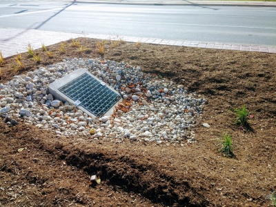
Flat metal overflow with stone surround to reduce erosion around the cast concrete structure. Mississauga Road, ON
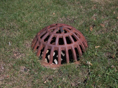
Domed, metal overflow grate. Being flush with the surface reduces potential infiltration of ponded water. Photo credit: Aaron Volkening
Overflow inlet for newly constructed stormwater bioretention areas in median of Bradley Road. Village of Brown Deer, Wisconsin. Bradley Road, east of 51st Street. Photo from October 2015. Constructed summer 2015.
Photo credit: Aaron Volkening
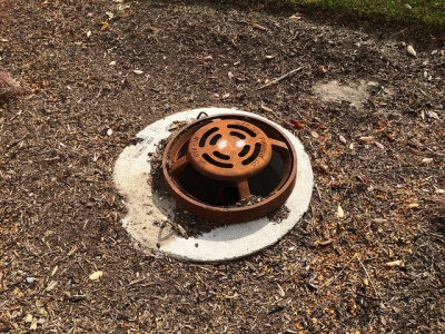
Flat, metal overflow grate in Emeryville California Stormwater Curb Extension
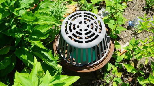
Note the greyish colour change indicating UV degradation of this plastic overflow inlet in a bioretention cell; metal is recommended instead. Mississauga ON.


