Inspection and Maintenance: Enhanced Swales
Overview[edit]
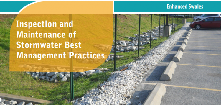
Enhanced swales are gently sloping vegetated open channels featuring a parabolic or trapezoidal cross-section and check dams, designed to convey and treat stormwater runoff (i.e., rainwater or snowmelt from roofs or pavements). The grading, Check dams and vegetation spreads out and slows down the flow of water, allowing suspended sediment and floatables (e.g., trash, natural debris, oil and grease) to settle out. A portion of the flowing water soaks into the soil and replenishes groundwater or is taken up by plant roots and evaporated back to the atmosphere. Runoff water is delivered to the practice through inlets such as curb cuts, spillways or other concrete structures, sheet flow from pavement edges, or pipes connected to catchbasins or roof downspouts. The planting bed and side slopes are typically covered with grasses or a mixture of flood tolerant, erosion resistant vegetation and stone. They do not feature filter media soil and sub-drains like bioretention or bioswales do. Water not ponded behind check dams or absorbed by the planting bed is conveyed to an adjacent drainage system (e.g., municipal storm sewer or other BMP) at the lowest downstream point by an outlet structure (e.g., ditch inlet catchbasin, culvert). Key components of this feature are described in further detail below.
Properly functioning enhanced swales reduce the quantity of pollutants and runoff being discharged to municipal storm sewers and receiving waters (i.e., rivers, lakes and wetlands). In addition to their SWM benefits, enhanced swales provide aesthetic value as attractive landscaped features.
Key components of Enhanced swales to pay close attention to are the:
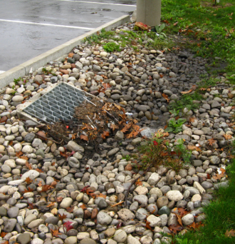
Trash, debris and sediment builds up at these locations and can prevent water from flowing into or out of the practice.
Associated Practices[edit]
- Grass Swales: A parabolic or trapezoidal-sized bottom, swale that contains grassed sloping sides and a filter media bottom to both convey overland flow and provide water treatment, and are often subject to more frequent maintenance. They generally contain an outlet structure at the lowest point for water to be sent to another LID BMP or the storm system; sometimes referred to as a roadside ditch. Does not contain check dams.
- Swales: Swales are linear landscape features consisting of a drainage channel with gently sloping sides. Underground they may be filled with engineered soil and/or contain a water storage layer of coarse gravel material. Two variations on a basic swale are recommended as low impact development strategies, although using a combination of both designs may increase the benefit.
- Bioswales are sometimes referred to as 'dry swales', 'vegetated swales', or 'water quality swales'. This type of BMP is form of bioretention with a long, linear shape (surface area typically >2:1 length:width) and a slope which conveys water and generally contains various water tolerant vegetation
Inspection and Testing Framework[edit]


Component |
Indicators |
Construction Inspection |
Assumption Inspection |
Routine Operation Inspection |
Verification Inspection |
|---|---|---|---|---|---|
| Contributing Drainage Area | |||||
| CDA condition | x | x | x | x | |
| Inlet | |||||
| Inlet/Flow Spreader Structural Integrity | x | x | x | ||
| Inlet/Flow Spreader Structural Integrity | x | x | x | x | |
| Pretreatment sediment accumulation | x | x | x | ||
| Inlet erosion | x | x | |||
| Perimeter | |||||
| BMP dimensions | x | x | x | ||
| Side slope erosion | x | x | |||
| Surface ponding area | x | x | x | ||
| Filter Bed | |||||
| Standing water | x | x | x | ||
| Trash | x | x | |||
| Filter bed erosion | x | x | |||
| Filter bed sediment accumulation | x | x | x | ||
| Surface ponding depth | x | x | x | ||
| Filter bed surface sinking | x | x | x | ||
| Check dams | x | x | x | x | |
| Planting Area | |||||
| Vegetation cover | x | x | x | x | |
| Vegetation condition | x | x | |||
| Vegetation composition | x | x | x | ||
| Outlet | |||||
| Overflow outlet obstruction | x | x | x | x |
Component |
Indicators |
Construction Inspection |
Assumption Inspection |
Routine Operation Inspection |
Verification Inspection | |
|---|---|---|---|---|---|---|
| Testing Indicators | ||||||
| Soil characterization testing | x | x | (x) | |||
| Sediment accumulation testing | x | x | x | x | ||
| Surface infiltration rate testing | x | (x) | ||||
| Natural or simulated storm event testing | x | (x) | ||||
| Note: (x) denotes indicators to be used for Performance Verification inspections only (i.e., not for Maintenance Verification inspections) | ||||||

Construction Inspection Tasks[edit]
Construction inspections take place during several points in the construction sequence, specific to the type of LID BMP, but at a minimum should be done weekly and include the following:
- During site preparation, prior to BMP excavation and grading to ensure the CDA is stabilized or that adequate ESCs or flow diversion devices are in place and confirm that construction materials meet design specifications
- At completion of excavation and grading, prior to installation of pipes/sewers and backfilling to ensure depths, slopes and elevations are acceptable
- Prior to hand-off points in the construction sequence when the contractor is responsible for the work changes (i.e., hand-offs between the storm sewer servicing, paving, building and landscaping contractors
- After every large storm event (e.g., 15 mm rainfall depth or greater) to ensure Erosion Sediment Controls (ESCs) and pretreatment or flow diversion devices are functioning and adequately maintained. View the table below, which describes critical points during the construction sequence when inspections should be performed prior to proceeding further. You can also download and print the table here

Construction Sequence Step & Timing |
Inspection Item |
Observations* |
|---|---|---|
| Site Preparation - after site clearing and grading, prior to BMP excavation and grading | Natural heritage system and tree protection areas remain fenced off | |
| ESCs protecting BMP layout area are installed properly | ||
| CDA is stabilized or runoff is diverted around BMP layout area | ||
| BMP layout area has been cleared and is staked/delineated | ||
| Benchmark elevation(s) are established nearby | ||
| Construction materials have been confirmed to meet design specifications | ||
| BMP Excavation and Grading - prior to landscaping | Excavation location, footprint, depth and slopes are acceptable | |
| Excavated soil is stockpiled outside the CDA | ||
| Embankments/berms (elevations, slopes, compaction) are acceptable | ||
| Excavation bottom and sides roughened to reduce smearing and compaction | ||
| Landscaping – after final grading, prior to planting | Topsoil depth, degree of compaction and surface elevations at inlets and outlets are acceptable | |
| Maximum surface ponding depth is acceptable | ||
| Filter bed is free of ruts, local depressions and not overly compacted | ||
| Planting material meets approved planting plan specifications (plant types and quantities) | ||
| Note: for Observation Column: S = Satisfactory; U = Unsatisfactory; NA = Not Applicable* | ||
Routine Maintenance - Key Components and I&M Tasks[edit]
Regular inspections (twice annually, at a minimum) done as part of routine maintenance tasks over the operating phase of the BMP life cycle to determine if maintenance task frequencies are adequate and determine when rehabilitation or further investigations into BMP function are warranted.
Table below describes routine maintenance tasks for bioretention practices, organized by BMP component, along with recommended minimum frequencies. It also suggests higher frequencies for certain tasks that may be warranted for BMPs located in highly visible locations or those receiving flow from high traffic areas (vehicle or pedestrian). Tasks involving removal of trash, debris and sediment and weeding/trimming of vegetation for BMPs in such contexts may need to be done more frequently (i.e., higher standards may be warranted).
Individuals conducting vegetation maintenance and in particular, weeding (i.e., removal of undesirable vegetation), should be familiar with the species of plants specified in the planting plan and experienced in plant identification and methods of removing/controlling noxious weeds. Key resources on these topics are provided below at the links provided:
- Agriculture and Agri-food Canada’s Weed Info database
- Ontario Ministry of Agriculture, Food and Rural Affairs’ Ontario Weed Gallery
- Ontario Ministry of Agriculture, Food and Rural Affairs’ Noxious Weeds In Ontario list
- Ontario Invasive Plant Council’s Quick Reference Guide to Invasive Plant Species
- Oregon State University Stormwater Solutions, 2013, Field Guide: Maintaining Rain Gardens, Swales and Stormwater Planters, Corvallis, OR.
- Plants of Southern Ontario (book), 2014, by Richard Dickinson and France Royer, Lone Pine Publishing, 528 pgs.
- Weeds of North America (book), 2014, by Richard Dickinson and France Royer, University of Chicago Press, 656 pgs.
| Component | Description | Inspection & Maintenance Tasks | (Pass) Photo Example | (Fail) Photo Example |
|---|---|---|---|---|
| Contributing Drainage Area (CDA) |
Area(s) from which runoff directed to the BMP originates; includes both impervious and pervious areas. |
|
||
| Pretreatment |
Devices or features that retain trash, debris and sediment; help to extend the operating life cycle; examples are eavestrough screens, catch basin inserts and sumps, oil and grit separators, geotextile-lined inlets, gravel trenches, grass filter strips and forebays. |
|
 The grass filter strip pretreatment is free of sediment, trash and debris. (Source: Abbey and Associates). |
 Sediment and debris has accumulated in the forebay and is preventing stormwater from flowing into the BMP |
| Inlets & Overflow Outlets |
Structures that deliver water to the BMP (e.g., Curb cuts, spillways, pavement edges, catch basins, pipes) or convey flow that exceeds the storage capacity of the BMP to another drainage system (i.e. other LID BMP, or storm sewer). |
|
||
| Perimeter |
Side slopes or structures that define the BMP footprint; may be covered by a mixture of vegetation, mulch and stone with slopes up to 3:1 (H:V), or concrete or masonry structures with vertical walls. |
|
||
| Filter Bed |
Linearly-oriented, gently sloping area (between 0.5 and 4% slope) where runoff is filtered and conveyed; parabolic or trapezoidal cross-section, lined with 20 to 30 cm of planting soil and covered with deep rooting perennial grasses or a mixture of vegetation and stone. |
|
 TThe maximum surface ponding depth behind check dams matches what was specified in the final design. (Source: Mark M. Holeman, Inc., 2015)[5] |
 The maximum ponding depth of the swale is significantly deeper than intended as the elevation of the check dam or overflow outlet is too high. (Source: Stiffler, 2012[6]) |
| Vegetation |
Deep rooting perennial grasses or a mixture of wildflowers and shrubs, tolerant to both wet and dry conditions and salt; roots uptake water and return it to the atmosphere, provide habitat for organisms that break down trapped pollutants and help maintain soil structure and permeability |
|
||
| Check dams |
Structures constructed of a non-erosive material, such as suitably sized aggregate, wood, gabions, riprap, stone or concrete; used to slow runoff water. Can be employed in practices such as bioswales and enhanced grass swales. Constructed across a drainage ditch, swale, or channel to lower the speed of concentrated flows for a certain design range of storm events and to promote infiltration. |
|


Tips to Preserve Basic BMP Function[edit]
- Because the risk of compaction is higher when topsoil is saturated, any maintenance tasks involving vehicle (e.g., ride mower) or foot traffic on the filter bed should not be performed during wet weather.
- Use push mower to maintain enhanced swales with grasses as vegetation cover or the lightest ride mower equipment available to minimize compaction of the filter bed.
- Use a mulching mower to maintain enhanced swales with grass as vegetation cover or leave clippings on the surface to help replenish organic matter and nutrients in the topsoil.
- Pruning of mature trees should be performed under the guidance of a Certified Arborist.
- Woody vegetation should not be planted or allowed to become established where snow will be piled/stored during winter.
- Removal of sediment accumulated on the filter bed surface should be performed by hand with rake and shovel, or vacuum equipment where feasible. If a small excavator is the chosen method, keep the excavator off the BMP footprint to avoid damage to side slopes/embankments and compaction of the topsoil.
Rehabilitation & Repair[edit]
Table below provides guidance on rehabilitation and repair work specific to enhanced grass swales organized according to BMP component.
| Component | Problem | Rehabilitation Tasks |
|---|---|---|
| Inlets |
Inlets are producing concentrated flow and causing filter bed erosion |
|
| Filter Bed | Local or average sediment accumulation ≥ 5 cm in depth. |
|
| Surface ponding remains for > 48 hours or surface infiltration rate is < 15 mm/h. |
| |
| Damage to filter bed or slide slope is present (e.g., erosion rills, animal burrows, sink holes, ruts) |
| |
| Vegetation |
Plants not thriving and planting soil is low in organic matter (<5%) or available phosphorus (<12 mg/kg) |
Inspection Time Commitments and Costs[edit]
Estimates are based on a typical partial infiltration bioretention design (i.e., includes a sub-drain); estimates for other designs (i.e., full infiltration and no-infiltration) can be found in the Low Impact Development (LID) Stormwater Management Practice Inspection and Maintenance Guide


Estimates of the life cycle costs of inspection and maintenance have been produced using the latest version of the LID Life Cycle Costing Tool for three design variations (full infiltration, partial infiltration and no infiltration) to assist stormwater infrastructure planners, designers and asset managers with planning and preparing budgets for potential LID features.
Assumptions for the above costs and the following table below are based on the following:
- Capital costs included within the category of construction include those related to site assessment, and conceptual and detailed design related tasks such as borehole analysis and soil testing. All material, delivery, labour, equipment (rental, operation, operator), hauling and disposal costs are accounted for within the construction costs of the facility. Standard union costs were derived from the RSMeans database in 2010 and have been adjusted for 5 year inflation of 8.79% (2010 to June, 2015).
- Costs include overhead and inflation to represent contractor pricing. It was assumed the practice is part of a new development (i.e., not a retrofit), thereby excluding (de)mobilization costs unless a particular piece of equipment would not normally have been present at the site. Additionally, it was assumed that excavated soil associated with construction of the BMP would be reused elsewhere on site. Overhead costs were presumed to consist of construction management (4.5%), design (2.5%), small tools (0.5%), clean up (0.3%) and other (2.2%).
- For maintenance frequencies and requirements and the life span of each practice are based on both literature and practical experience. Life cycle and associated maintenance costs are evaluated over a 50 year timeframe, which is the typical period over which infrastructure decisions are made.
- For enhanced grass swales it is assumed that some rehabilitation (e.g., rehabilitative maintenance) work will be needed on the filter bed surface once the BMP reaches 25 and 50 years of age in order to maintain functional drainage performance at an acceptable level. Included in the rehabilitation costs are (de)mobilization costs, as equipment would not have been present on site. Design costs were not included in the rehabilitation as it was assumed that the original LID practice design would be used to inform this work. The annual average maintenance cost does not include rehabilitation costs and therefore represents an average of routine maintenance tasks, as outlined in the Table under section, Routine Maintenance - Key Components and I&M Tasks above. All cost value estimates represent the net present value (NPV) as the calculation takes into account average annual interest (2%) and discount (3%) rates over the evaluation time periods.
- For all enhanced swale design variations, the CDA has been defined as a 2,000 m2 impervious pavement area plus the footprint area of a bioretention cell that is 133 m2 in size, as per design recommendations. The impervious area to pervious area ratio (I:P ratio) used to size the BMP footprint is 15:1, which is the maximum ratio recommended in the LID SWM Planning and Design Guide (CVC & TRCA, 2010)[11]. It is assumed that water drains to the cell through curb inlets spaced 6 m apart with stone cover on the filter bed at the inlets to dissipate the energy of the flowing water.
- Estimates of the life cycle costs of Enhanced Swales in Canadian dollars per unit CDA ($/m2) are presented in the table below. The LID Life Cycle Costing Tool allows users to select what BMP type and design variation applies, and to use the default assumptions to generate planning level cost estimates.
- Users can also input their own values relating to a site or area, design, unit costs, and inspection and maintenance task frequencies to generate customized cost estimates, specific to a certain project, context or stormwater infrastructure program.
- For all BMP design variations and maintenance scenarios, it is assumed that rehabilitation of part or all of the filter bed surface will be necessary once the BMP reaches 25 and 50 years of age to maintain acceptable surface drainage performance (e.g., surface ponding drainage time). Filter bed rehabilitation for enhanced swales is assumed to typically involve the tasks outlined under section, Routine Maintenance - Key Components and I&M Tasks above.

Notes:
- Estimated life cycle costs represent NPV of associated costs in Canadian dollars per square metre of CDA ($/m2).
- Average annual maintenance cost estimates represent NPV of all costs incurred over the time period and do not include rehabilitation costs.
- Rehabilitation cost estimates represent NPV of all costs related to repair work assumed to occur every 25 years including those associated with inspection and maintenance over a two (2) year establishment period for the plantings.
- Life cycle costs are very similar but slightly lower for BMPs constructed with filter sock or rock check dams, than concrete ones due to differences in material and labor unit costs.
- Rehabilitation costs are estimated to be between 24.4 to 28.1% of the original construction costs for High Frequency and Minimum Recommended maintenance program scenarios, respectively.
- Maintenance and rehabilitation costs over a 25 year time period are estimated to be 1.77 to 2.66 times the original construction cost, for the Minimum Recommended and High Frequency maintenance scenarios respectively, depending on check dam construction material.
- Maintenance and rehabilitation costs over a 50 year time period are estimated to be 3.13 and 4.74 times the original construction cost for the Minimum Recommended and High Frequency maintenance scenarios respectively, depending on check dam construction material.
Inspection Field Data Sheet[edit]
Feel free to download (downward facing arrow on the top righthand side) and print (Pinter emoticon on top right hand side) the following Enhanced Swale Inspection Field Data Form developed by TRCA, STEP and its partners for the Low Impact Development Stormwater Management Practice Inspection and Maintenance Guide[13].
The 6 page document prompts users to fill out details previously mentioned above on this page in other sections about various zones associated with Enhanced swale features (i.e. inlets, perimeter of the feature, filter bed, outlets, etc.) and describe why each area is a pass or fail, and if remediate action is required and under what timeframe it would be completed by. Furthermore, the forms prompt the reviewer to determine what type of inspection is being conducted for the feature in question: Construction (C), Routine Operation (RO), Maintenance Verification (MV), or Performance Verification (PV).

References[edit]
- ↑ TRCA. 2016. Fact Sheet - Inspection and Maintenance of Stormwater Best Management Practices: Enhanced Swales. https://sustainabletechnologies.ca/app/uploads/2018/02/Enhanced-Swales-Fact-Sheet.pdf
- ↑ 2.0 2.1 Toronto and Region Conservation Authority (TRCA). 2019. Erosion and Sediment Control Guideline for Urban Construction. Toronto and Region Conservation Authority, Vaughan, Ontario. https://sustainabletechnologies.ca/app/uploads/2020/01/ESC-Guide-for-Urban-Construction_FINAL.pdf
- ↑ Connop S. and Nash, C. 2019. A Storm in a Bioswale: Breaking Down Barriers to Nature-Based Solutions. The Nature of Cities. 16 December 2019 Accessed: 4 July 2022. https://www.thenatureofcities.com/2019/12/16/a-storm-in-a-bioswale-breaking-down-barriers-to-nature-based-solutions/
- ↑ Vidacycle. 2020. Soil Monitoring Guide: Other Soil Tests. Accessed 4 July 2022. https://soils.vidacycle.com/soil-tests/
- ↑ Mark M. Holeman, Inc. 2015. What is a Bio-Swale? Authored by Rick Blankenship. 25 September 2015. Accessed 5 July 2022. http://www.holemanlandscape.com/2015/09/25/what-is-a-bio-swale/
- ↑ Stiffler, L. 2012.RAIN GARDEN REALITY CHECK: Comparing LID to conventional system failures. Authored by: Eric De Place. 18 April 2012. Sightline Institute. Sustainable Living Series. Accessed 5 July 2022. https://www.sightline.org/2012/04/18/rain-garden-reality-check/
- ↑ TRCA. 2018. Inspection and Maintenance of Stormwater Best Management Practices - Enhanced Swales. Fact Sheet. https://sustainabletechnologies.ca/app/uploads/2018/02/Enhanced-Swales-Fact-Sheet.pdf
- ↑ TRCA. 2018. Inspection and Maintenance of Stormwater Best Management Practices. Bioretention - Fact Sheet. https://sustainabletechnologies.ca/app/uploads/2018/02/Bioretention-and-Dry-Swales-Fact-Sheet.pdf
- ↑ TRCA. 2018. Inspection and Maintenance of Stormwater Best Management Practices. Bioretention - Fact Sheet. https://sustainabletechnologies.ca/app/uploads/2018/02/Bioretention-and-Dry-Swales-Fact-Sheet.pdf
- ↑ TRCA. 2018. Inspection and Maintenance of Stormwater Best Management Practices. Bioretention - Fact Sheet. https://sustainabletechnologies.ca/app/uploads/2018/02/Bioretention-and-Dry-Swales-Fact-Sheet.pdf
- ↑ CVC and TRCA. 2010. Low Impact Development Stormwater Management Planning and Design Guide. Version 1.0. https://cvc.ca/wp-content/uploads/2014/04/LID-SWM-Guide-v1.0_2010_1_no-appendices.pdf
- ↑ TRCA. 2018. Inspection and Maintenance of Stormwater Best Management Practices. Bioretention - Fact Sheet. https://sustainabletechnologies.ca/app/uploads/2018/02/Bioretention-and-Dry-Swales-Fact-Sheet.pdf
- ↑ STEP. 2016. Low Impact Development Stormwater Management Practice Inspection and Maintenance Guide. https://sustainabletechnologies.ca/app/uploads/2016/08/LID-IM-Guide-2016-1.pdf