Difference between revisions of "Infiltration trenches"
Jenny Hill (talk | contribs) m (→Design) |
Jenny Hill (talk | contribs) m |
||
| (2 intermediate revisions by the same user not shown) | |||
| Line 4: | Line 4: | ||
{{TOClimit|2}} | {{TOClimit|2}} | ||
==Overview== | ==Overview== | ||
| + | {{float right|{{#widget:YouTube|id=DLXsb1FwKD4}}}} | ||
As their name suggests infiltration trenches work primarily to infiltrate and convey stormwater. They are an underground facility and are excellently suited to connecting other components in the treatment train. | As their name suggests infiltration trenches work primarily to infiltrate and convey stormwater. They are an underground facility and are excellently suited to connecting other components in the treatment train. | ||
{{textbox|1=Infiltration trenches are an ideal technology for: | {{textbox|1=Infiltration trenches are an ideal technology for: | ||
| Line 17: | Line 18: | ||
==Design== | ==Design== | ||
| − | |||
===Sizing=== | ===Sizing=== | ||
'''[[Infiltration: Sizing and modeling]]''' | '''[[Infiltration: Sizing and modeling]]''' | ||
| Line 34: | Line 34: | ||
==Construction== | ==Construction== | ||
| − | + | *[[Construction]] | |
| + | |||
==Gallery== | ==Gallery== | ||
{{:Infiltration trenches: Gallery}} | {{:Infiltration trenches: Gallery}} | ||
Revision as of 19:16, 18 June 2019
This article is about underground systems which distribute concentrated flow along a level, linear facility to promote infiltration to native soils.
For a similar structure, which differs in being designed to receive excess flow and convey it, whilst promoting infiltration to native soils, see exfiltration trenches.

Overview[edit]
As their name suggests infiltration trenches work primarily to infiltrate and convey stormwater. They are an underground facility and are excellently suited to connecting other components in the treatment train.
Infiltration trenches are an ideal technology for:
- Installing below any type of surface or landscape
- Balancing the requirements to infiltrate excess stormwater whilst conveying excess
The fundamental components of an infiltration trench are:
- Layers of coarse aggregate to bed the pipe, store and redistribute water.
- Perforated pipe
- Geotextile
Planning considerations[edit]
As shown in the illustration above a surface inlet to an infiltration trench may simply be a channel of decorative stone supported by a geotextile. So that at grade it may be indistinguishable from a gravel diaphragm. In function though, the decorative surface course of the infiltration trench needs to remain free-draining down into the trench, whereas the gravel diaphragm is designed to spill over onto adjacent land, leaving sediment behind in the gravel or stone channel.
Design[edit]
Sizing[edit]
Infiltration: Sizing and modeling
- Virginia up to 10' (3 m) deep. [1]
- Minnesota up to 12' (3.6 m) deep. [2]
- "...not normally be deeper than 3 to 4 m in order to maximise the length of the flow path to the water table through the unsaturated zone." [3]
- There is a cost implication with digging deeper practices, trench boxes may be required to retain the side walls during construction.
Materials[edit]
Aggregate[edit]
This article gives recommendations for aggregate to be used to store water for infiltration. This is usually called 'clear stone' at aggregate yards.
To see an analysis of Ontario Standard Specifications for granular materials, see OPSS aggregates.
For advice on decorative surface aggregates see Stone
Gravel used for underdrains in bioretention, infiltration trenches and chambers, and exfiltration trenches should be 20 or 50 mm, uniformly-graded, clean (maximum wash loss of 0.5%), crushed angular stone that has a porosity of 0.4[4].
The clean wash to prevent rapid accumulation of fines from the aggregate particles in the base of the reservoir. The uniform grading and the angularity are important to maintain pore throats and clear voids between particles. (i.e. achieve the porosity). Porosity and permeability are directly influenced by the size, gradation and angularity of the particles [5]. See jar test for on-site verification testing protocols.
Gravel with structural requirements should also meet the following criteria:
- Minimum durability index of 35
- Maximum abrasion of 10% for 100 revolutions and maximum of 50% for 500 revolutions
Standard specifications for the gradation of aggregates are maintained by ASTM D2940
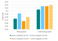
The highest porosity is found in uniformly graded aggregate, as there are no smaller particles to occupy the inter-particle pores. [5]
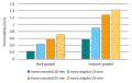
Higher permeability is found in larger, angular, uniformly graded aggregate. This is due to larger pore sizes and lower tortuosity. [5]


Perforated Pipe[edit]

Perforated pipes are a common component of underdrains used in bioretention, permeable pavements, infiltration trenches and exfiltration systems.
Pipes should be manufactured in conformity with the latest standards by the Canadian Standards Association (CSA) or ASTM International.
- Perforated pipes should be continuously perforated, smooth interior HDPE or PVC.
- Wherever possible pipes should be ≥200 mm internal diameter to reduce potential of freezing and to facilitate push camera inspections and cleaning with jet nozzle equipment.
- Smooth interior facilitates inspection and maintenance activities; internal corrugations can cause cameras or hydrojetting apparatus to become snagged.
- A perforated pipe with many rectangular slots has better drainage characteristics than a pipe with similar open area provided by fewer circular holes [6].
- Non-perforated pipes should be used for conveyance of stormwater to and from the facility, including overflow. It is good practice to extend the solid pipe approximately 300 mm within the reservoir or practice to reduce the potential for native soil migration into the pipe.
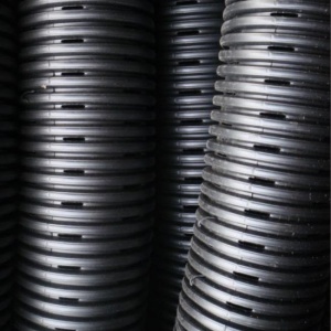
Pipe with slotted perforations
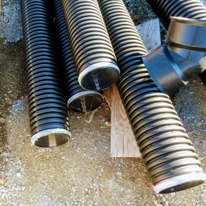
Perforated pipes awaiting installation, note the 45 degree couplings used to facilitate push camera inspection and jet nozzle cleaning.


See also: Flow through perforated pipe
Construction[edit]
Gallery[edit]
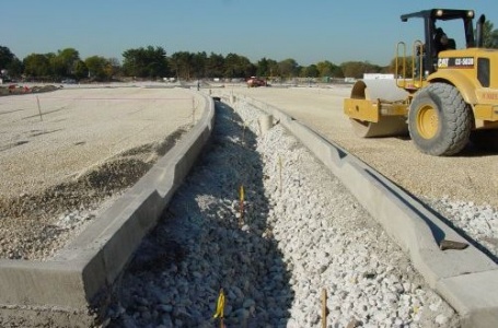
Trench laid in advance of the surrounding catchment being finished. This system would benefit from some geotextile on the surface to prevent sediment from accumulating before the asphalt is laid.
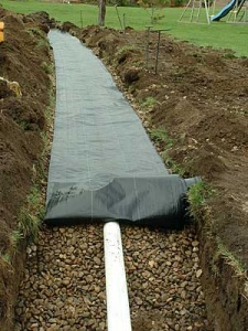
Good use of geotextile, being limited to preventing fines from entering the trench from above.

View of infiltration trench in U.S. Photo credit: Moreau1


- ↑ Viriginia Department of Transport. (2010). VDOT BMP Design Manual of Practice. Retrieved March 15, 2018, from http://www.virginiadot.org/business/resources/LocDes/BMP_Design-Manual/Chapter_8_Infiltration_Trench.pdf
- ↑ Design criteria for Infiltration trench. (2016, September 21). Minnesota Stormwater Manual, . Retrieved 13:25, April 4, 2018 from https://stormwater.pca.state.mn.us/index.php?title=Design_criteria_for_Infiltration_trench&oldid=28702.
- ↑ Design of soakaways (2015) www.tiipublications.ie/library/DN-DNG-03072-01.pdf
- ↑ Porosity of Structural Backfill, Tech Sheet #1, Stormtech, Nov 2012, http://www.stormtech.com/download_files/pdf/techsheet1.pdf accessed 16 October 2017
- ↑ 5.0 5.1 5.2 Judge, Aaron, "Measurement of the Hydraulic Conductivity of Gravels Using a Laboratory Permeameter and Silty Sands Using Field Testing with Observation Wells" (2013). Dissertations. 746. http://scholarworks.umass.edu/open_access_dissertations/746
- ↑ Hazenberg, G., and U. S. Panu (1991), Theoretical analysis of flow rate into perforated drain tubes, Water Resour. Res., 27(7), 1411–1418, doi:10.1029/91WR00779.