Infiltration chambers
Overview[edit]
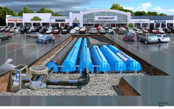
As their name suggests infiltration chambers work exclusively to infiltrate stormwater. Infiltration chambers include a range of proprietary manufactured, modular structures embedded in clean, crushed angular stone that are installed underground, typically under parking or landscaped areas, that create large void spaces for temporary storage of stormwater, allowing it to infiltrate into the underlying native soil. They may be designed to provide sufficient load bearing capacity to allow construction of structures on top of them. They can be installed individually or in series, in trench or bed configurations. Due to the large volume of underground void space they create, and the modular nature of their design, they are well suited to sites where available space for other types of BMPs is limited, or where it is desirable for the facility to have little or no surface footprint (e.g., high density development contexts).
Infiltration chambers are an ideal technology for:
- Installing below any type of surface or landscape
- Receiving and infiltrating large volumes of water
Take a look at the downloadable Soakaways, Infiltration Trenches & Chambers Factsheet below for a .pdf overview of this LID Best Management Practice:

The fundamental components of an infiltration chamber system are:
- Pretreatment devices to retain trash, debris, sediment and floatables and prevent clogging of inlets, underlying native soil and outlets;
- Storage reservoir consisting of structurally reinforced chambers, vaults, crates, perforated pipes or other void-forming structures embedded in coarse aggregate;
- Pipes and possibly flow control structures to convey water into and out of the practice; and
- Geotextiles to maintain separation between the storage reservoir and surrounding native soil.
| System type | Perforated pipes | Vaults | Arched chambers | Crates |
|---|---|---|---|---|

|

|

|

| |
| Materials | Plastic or Metal | Concrete | Plastic | Plastic |
| Footprint | Medium | Small | Medium | Small |
| Stackable | Yes | No | Yes | Yes |
| Effective Porosity (n') | 0.60 - 0.65 | 0.75 - 0.85 | 0.50 - 0.65 | 0.95 |
| Maintenance Access | Moderate | Excellent | Moderate | Difficult |
| Standard Strength | H-20 | H-25 | H-20 | H-20 - H-25 |
Planning Considerations[edit]
All types of modular infiltration systems require a bedding of angular clear stone to permit infiltration, and provide a foundation for the installation:
- Plastic chambers usually have a parabolic shape to support the load above. The spaces between rows of plastic pipes or chambers are filled with clear stone to support overlying structures.
- Concrete vaults and plastic crates are often rectangular-shaped. Concrete vault systems can, in some circumstances, be employed without any additional cover. However, a minimum of 20 cm cover is recommended for most applications. Where this cover is planting soil this can support turf grass. Greater planting soil depths are required to support more deeply rooting plants like perennials and shrubs (45 to 60 cm) and trees (85 to 100 cm).
Infiltration[edit]
For information about constraints to infiltration practices, and approaches and tools for identifying and designing within them see Infiltration.
Geometry and Site Layout[edit]
Infiltration chambers and soakaways can be designed in a variety of shapes, although facilities should have level or nearly level bottoms to spread flow evenly throughout. Typically designed with an impervious drainage area to pervious facility footprint area ratio (i.e. I:P ratio) between 5:1 on low permeability soils (HSG C & D) to 20:1 on high permeability soils (HSG A & B). Not typically deeper than 4 m.
Native Soil[edit]
Infiltration trenches, chambers and soakaways can be constructed over any soil type, but hydrologic soil group (HSG) A or B soils are best for achieving water balance and erosion control objectives. Facilities should be located on portions of the site with the highest infiltration rates. Native soil infiltration rate at the proposed facility location and depth should be confirmed through in-situ measurements of hydraulic conductivity under field saturated conditions. For guidance on infiltration testing and selecting a design infiltration rate see Design infiltration rate.
Wellhead Protection[edit]
Facilities receiving road or parking lot runoff should not be located within two (2) year time-of-travel wellhead protection areas (see drinking water source protection plan).
Available Space[edit]
Recommended under parking, walkway or landscape areas and require little surface space, solely for inlets, outlets and access structures.
Site Topography[edit]
Facilities cannot be located on natural slopes greater than 15%.
Water Table[edit]
Maintaining a separation of one (1) metre between the elevations of the base of the practice and the seasonally high water table, or top of bedrock is recommended. Lesser or greater values may be considered based on groundwater mounding analysis. See Groundwater for further guidance and spreadsheet tool.
Pollution Hot Spot Runoff[edit]
To protect groundwater from possible contamination, runoff from pollution hot spots should not be treated by infiltration trenches, chambers or soakaways.
Proximity to Underground Utilities[edit]
Designers should consult local utility design guidance for the horizontal and vertical clearances required between storm drains.
Karst[edit]
Infiltration trenches, chambers and soakaways are not suitable in areas of known or implied karst topography.
Setback from Buildings[edit]
Facilities should be setback a minimum of four (4) metres from building foundations.
For a table summarizing information on planning considerations and site constraints see Site considerations.
See above an example of a infiltration chamber system. This is a sample vendor video – similar videos and descriptions can be found on other vendor websites – see below for list of vendors under the External links section. In our effort to make this guide as functional as possible, we have decided to include these proprietary systems and links to manufacturers websites. Note - Inclusion of such links does not constitute endorsement by the Sustainable Technologies Evaluation Program.
Design[edit]
Inlets[edit]
Recommended to distribute inflow between multiple inlets to reduce risk of failure. May include delivery of runoff to the facility as concentrated overland or concentrated underground (i.e. pipe) flow. For concentrated overland flow:
- Catch basins or other inlet structures should be located at all sag points in the gutter grade and immediately upgrade of median breaks, crosswalks and street intersections,
- inlet types include curb openings, side inlet catch basins, trench drains, and other pre-fabricated inlet structures,
- spillways aid in turning flow 30, 45 or 90 degrees into the practice,
- if the inlet structure itself does not provide sedimentation or filtration pre-treatment, incorporate a geotextile and stone filter inlet at curb opening or spillway locations to isolate sediment, trash and debris for ease of removal, and
- provide a 50 to 100 mm drop in elevation between inlet invert and top elevation of the stone cover.
For concentrated underground flow, inlets may include plastic or concrete pipes from roof drains or catch basins, storm sewers, OGSs or outlet leader from an upstream BMP. Solid pipe transitions to perforated pipe within the storage reservoir 0.3 m from the sides. Trench plugs should be installed around solid pipes where they enter and exit the storage reservoir.
Pre-Treatment[edit]
It is important to prevent sediment, trash and debris from entering infiltration facilities because they could contribute to clogging and failure of the system. Infiltration practices may be used to treat runoff from roofs and pavements with sedimentation or filtration pre-treatment. The following pre-treatment options help facilitate maintenance and reduce risk of failure by confining sediment and debris to an accessible area, thereby reducing the potential for system clogging:
- Leaf screens are mesh screens installed either on the building eavestroughs or roof downspouts and are used to remove leaves and other large debris from roof runoff.
- Catch basin, manhole or other inlet structure sumps in combination with a shield, baffle, trap, or filter insert device, or goss trap, are used to pre-treat concentrated overland flow. They can be designed to retain both coarse and fine particulate sediments in the sump, and floatables (hydrocarbons, trash and debris). A variety of proprietary pre-treatment devices are available.
- Oil and grit (hydrodynamic) separators (OGS) are used for concentrated underground flow.
- Infiltration chambers are designed with an isolated filter row at inlets, not connected by pipes to the other chambers, that isolates the bulk of sediment and associated pollutants and is designed for ease of access by jet flushing cleaning equipment.
- Grass swales can be used to pre-treat road and parking lot runoff . Provide a 75 to 150 mm elevation drop between the inlet invert and swale surface.
- Geotextile and stone filter inlets are, square or rectangular curb openings located directly over the practice, filled with clean aggregate, covered with a layer of geotextile filter fabric and stone, graded level and installed at concentrated overland flow inlets. Elevation change of 75 to 100 mm from pavement to top of the stone cover. Stone cover may be 50 to 150 mm diameter crushed angular stone, river rock/beach stone or rip rap.
Storage Reservoir[edit]
Depth must meet both runoff storage and structural support requirements. See STEP LID Planning and Design Guide wiki page, Infiltration: Sizing and modeling, for guidance and spreadsheet tool for determining the reservoir depth and area required to store the design storm runoff volume. Should be filled with uniformly graded, washed 25 or 50 mm diameter crushed angular stone (max. wash loss of 0.5%) with a porosity of 0.4. For facilities located under load-bearing structures like pavements, aggregate should have a minimum durability index of 35, and a maximum abrasion of 10% for 100 revolutions and 50% for 500 revolutions. Include organic material derived from untreated wood (e.g. chips, mulch or shavings) to enhance nitrogen removal.
Void-forming structures[edit]
Includes chambers, vaults, crates or perforated pipes that provide large water storage volume per unit area, reduce required facility footprint area and conserve aggregate. Plastic chamber systems should be compliant with CSA B184 SERIES 11 (R2015) or ASTM F2418-16A. Maximum allowable load for plastic chambers must be determined in accordance with ASTM F2787-13. Concrete vault systems should be compliant with CSA A23.3-14 and CSA A23.1-09/A23.2-09 (R2014) or ASTM C858-10e1. See manufacturer for product specific specifications regarding maximum load, minimum cover depth and porosity or water storage per unit area.
Geotextile[edit]
Storage reservoirs should be lined on the sides and top with geotextile filter fabric to maintain separation from the native soil. Geotextile on the base is optional but may be prone to blinding and eventual clogging. Material specifications should conform to Ontario Provincial Standard Specification (OPSS) 1860 for Class II geotextile fabrics. Should be woven monofilament or non-woven needle punched, or woven monofilament with a minimum overlap of 300 mm. Woven slit film and non-woven heat bonded fabrics should not be used as they are prone to clogging. Specification of geotextile fabrics should consider the apparent opening size (AOS) for non-woven fabrics, or percent open area (POA) for woven fabrics, to maintain water flow even with sediment and microbial film build-up. Other factors that need consideration include maximum forces to be exerted on the fabric, and the load bearing ratio, texture (i.e., grain size distribution) and permeability of the native soil in which they will be installed. Geotextile socks around perforated pipes should conform to ASTM D6707 with minimum water flow rate conforming to ASTM D4491 (12,263 L/min/m2 at 5 cm head).
Perforated pipes[edit]
Continuously perforated, smooth interior HDPE or PVC drainage pipe, ≥200 mm interior diameter where possible to reduce risk of freezing and facilitate push camera inspection and cleaning with jet nozzle equipment. Including geotextile socks around perforated pipes is optional. May include an orifice plate or valve flow restrictor to provide erosion control and optimize infiltration.

Conveyance and Overflow[edit]
Typically designed to be offline where a flow control structure or inlet allows only the design storm runoff volume to enter the facility. Excess flows are conveyed to a downstream storm sewer or other BMP by a flow-splitting manhole (i.e. flow through riser) containing a weir and overflow outlet pipe, or by by-passing the curb opening and flowing into a down-gradient catch basin. Overflow structures must be sized to safely convey large event flows. The overflow outlet should be below the maximum frost penetration depth (i.e. frost line) to function year round.
Monitoring Wells[edit]
Recommended for monitoring drainage time between storms. Monitoring well should be a vertical standpipe consisting of an anchored 100 to 150 mm diameter pipe with perforations along the length within the reservoir, installed to the bottom of the facility, with a lockable cap. Flow-splitting manholes may also be used for drainage time monitoring.
Access Structures[edit]
Manholes or maintenance hatches connected to infiltration chambers, or standpipe inspection ports connected to infiltration trench or soakaway perforated pipe that provide access for inspection and maintenance. Should be installed at inlets and outlets at a minimum. Couplings used for standpipe connections should be 45° to facilitate pipe access by push camera and jet nozzle cleaning equipment.

(Philadelphia Water Department, 2020)[2]
The above image depicts various types of infiltration chamber systems that can be installed underneath a impermeable surface, such as a parking lot or commercial property site (see table in Overview Section above for further details on each of the configurations shown). Note the observation well (or monitoring well) shown which provides access for general I&M of the BMP.
Ability to Meet Stormwater Criteria[edit]
| BMP Type | Water Balance | Water Quality | Erosion Control |
|---|---|---|---|
| Infiltration Trenches,
Chambers and Soakaways |
Yes | Yes | Yes |
Materials[edit]
Chambers[edit]
Plastic chambers[edit]
Chambers should be compliant with:
- CSA B184-17 "Polymeric subsurface stormwater management structures".
- ASTM F2418-16a “Standard Specification for Polypropylene (PP) Corrugated Wall Stormwater Collection Chambers”.
Allowable loads for the chambers must be determined in accordance with ASTM F2787-13 “Standard Practice for Structural Design of Thermoplastic Corrugated Wall Stormwater Collection Chambers”.
Concrete vaults[edit]
Concrete vault-type systems should be compliant with:
- CSA A23.3-14 "Design of concrete structures",
- CSA A23.1-09/A23.2-09 (R2014) "Concrete materials and methods of concrete construction/Test methods and standard practices for concrete", and
- ASTM C858 - 10e1 "Standard Specification for Underground Precast Concrete Utility Structures".
Aggregates[edit]
This article gives recommendations for aggregate to be used to store water for infiltration. This is usually called 'clear stone' at aggregate yards.
To see an analysis of Ontario Standard Specifications for granular materials, see OPSS aggregates.
For advice on decorative surface aggregates see Stone
Gravel used for underdrains in bioretention, infiltration trenches and chambers, and exfiltration trenches should be 20 or 50 mm, uniformly-graded, clean (maximum wash loss of 0.5%), crushed angular stone that has a porosity of 0.4[3].
The clean wash to prevent rapid accumulation of fines from the aggregate particles in the base of the reservoir. The uniform grading and the angularity are important to maintain pore throats and clear voids between particles. (i.e. achieve the porosity). Porosity and permeability are directly influenced by the size, gradation and angularity of the particles [4]. See jar test for on-site verification testing protocols.
Gravel with structural requirements should also meet the following criteria:
- Minimum durability index of 35
- Maximum abrasion of 10% for 100 revolutions and maximum of 50% for 500 revolutions
Standard specifications for the gradation of aggregates are maintained by ASTM D2940
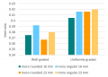
The highest porosity is found in uniformly graded aggregate, as there are no smaller particles to occupy the inter-particle pores. [4]
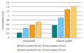
Higher permeability is found in larger, angular, uniformly graded aggregate. This is due to larger pore sizes and lower tortuosity. [4]


Other[edit]
Construction[edit]
Oil Disturbance and Compaction[edit]
Before site work begins, locations of facilities should be clearly marked. Ideally, infiltration practice locations should remain outside the limit of disturbance until construction of the facility begins to prevent soil compaction by heavy equipment.
Excavation[edit]
If >2.0 m in depth, trench shorings will be required to support the sidewalls. Use a toothed bucket to excavate and roughen the excavation bottom and sides prior to backfilling.
Erosion and Sediment Control[edit]
Infiltration practice locations should not be used as sediment basins during construction. To prevent sediment from clogging, erosion and sediment controls should remain in place and runoff should be diverted from the infiltration facility until the contributing drainage area is fully stabilized and sediment removal from catch basins, pre-treatment devices and maintenance hole sumps has been completed.
Inspection and Maintenance[edit]
Infiltration trenches, chambers and soakaways will continue to function during winter months if the overflow outlet is located below the local maximum frost penetration depth (i.e. frost line).
Routine inspection and maintenance consists of checking and cleaning trash, debris and sediment from pre-treatment devices, inlets and outlets twice a year in the spring and/or late fall, or when pre-treatment device sump is half full. Use hydro-vac truck to remove sediment from catch basin sumps, OGS and isolated chamber row filter pre-treatment devices. To clean isolated chamber row filters use a vacuum truck equipped with rear-facing jet nozzle for cleaning large diameter pipes or culverts.
Monitoring of storage reservoir water level during and after natural or simulated storm events using the monitoring well should be performed periodically to verify the facility drains within the required drainage time (typically 72 hours). Should be performed as part of inspections following construction or major rehabilitation prior to assumption, and every 15 years at a minimum, to track drainage performance over time and determine when replacement is needed.
Take a look at the Inspection and Maintenance: Underground Infiltration Systems page by clicking below for further details about proper inspection and maintenance practices:

Gallery[edit]
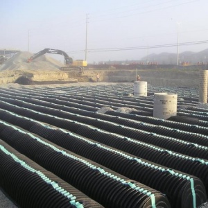
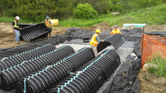
Infiltration chambers being installed.
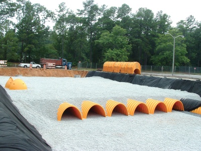
Chamber systems can be very large, both in terms of depth and footprint...
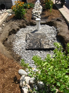
...or very small as this residential soakaway/dry well.

Parking lot stormwater detention system, partially installed. Photo credit: Arbitrarily0

Contractors construct an underground soakaway on the runway extension of Taxiway Alpha as shown here Oct. 5, 2012, at RAF Mildenhall, England. Photo credit: Karen Abeyasekere
Infiltration chambers being installed.
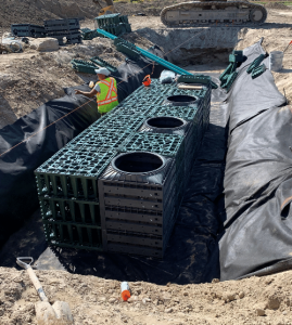
Example of "crate style" Infiltration chambers being installed in East Gwillimbury. Photo credit: Make-Way Environmental Technologies Inc.


External links[edit]
In our effort to make this guide as functional as possible, we have decided to include proprietary systems and links to manufacturers websites.
Inclusion of such links does not constitute endorsement by the Sustainable Technologies Evaluation Program.
Lists are ordered alphabetically; link updates are welcomed using the form below.
Plastic chambers[edit]
- ADS chambers design tool
- Armtec
- Echelon
- Cultec
- Nilex
- Triton
- Make-Way Environmental Technologies Inc.
- Prinsco
- NDS Stormchambers
Concrete chambers[edit]
References[edit]
- ↑ Young, D. Van Seters, T., Graham, C. 2013. Evaluation of Underground Stormwater Infiltration Systems. Toronto and Region Conservation Authority. Toronto, Ontario.
- ↑ Philadelphia Water Department. 2020. Stormwater Management Guidance Manual: Version 3.2. Accessed from: https://www.pwdplanreview.org/upload/manual_pdfs/PWD-SMGM-v3.2-20201001.pdf
- ↑ Porosity of Structural Backfill, Tech Sheet #1, Stormtech, Nov 2012, http://www.stormtech.com/download_files/pdf/techsheet1.pdf accessed 16 October 2017
- ↑ 4.0 4.1 4.2 Judge, Aaron, "Measurement of the Hydraulic Conductivity of Gravels Using a Laboratory Permeameter and Silty Sands Using Field Testing with Observation Wells" (2013). Dissertations. 746. http://scholarworks.umass.edu/open_access_dissertations/746