Difference between revisions of "Infiltration chambers"
(→Design) |
|||
| Line 70: | Line 70: | ||
Facilities should be setback a minimum of four (4) metres from building foundations. | Facilities should be setback a minimum of four (4) metres from building foundations. | ||
| − | ==Design | + | ==Design== |
===Sizing=== | ===Sizing=== | ||
[[Infiltration: Sizing and modeling]] | [[Infiltration: Sizing and modeling]] | ||
Revision as of 20:37, 26 August 2021
Overview[edit]
As their name suggests infiltration chambers work exclusively to infiltrate stormwater. Infiltration chambers include a range of proprietary manufactured, modular structures embedded in clean, crushed angular stone that are installed underground, typically under parking or landscaped areas, that create large void spaces for temporary storage of stormwater, allowing it to infiltrate into the underlying native soil. They may be designed to provide sufficient load bearing capacity to allow construction of structures on top of them. They can be installed individually or in series, in trench or bed configurations. Due to the large volume of underground void space they create, and the modular nature of their design, they are well suited to sites where available space for other types of BMPs is limited, or where it is desirable for the facility to have little or no surface footprint (e.g., high density development contexts).
Infiltration chambers are an ideal technology for:
- Installing below any type of surface or landscape
- Receiving and infiltrating large volumes of water
The fundamental components of an infiltration chamber system are:
- Pretreatment devices to retain trash, debris, sediment and floatables and prevent clogging of inlets, underlying native soil and outlets;
- Storage reservoir consisting of structurally reinforced chambers, vaults, crates, perforated pipes or other void-forming structures embedded in coarse aggregate;
- Pipes and possibly flow control structures to convey water into and out of the practice; and
- Geotextiles to maintain separation between the storage reservoir and surrounding native soil.
| System type | Perforated pipes | Vaults | Arched chambers | Crates |
|---|---|---|---|---|

|

|

|

| |
| Materials | Plastic or Metal | Concrete | Plastic | Plastic |
| Footprint | Medium | Small | Medium | Small |
| Stackable | Yes | No | Yes | Yes |
| Effective Porosity (n') | 0.60 - 0.65 | 0.75 - 0.85 | 0.50 - 0.65 | 0.95 |
| Maintenance Access | Moderate | Excellent | Moderate | Difficult |
| Standard Strength | H-20 | H-25 | H-20 | H-20 - H-25 |
Planning Considerations[edit]
All types of modular infiltration systems require a bedding of angular clear stone to permit infiltration, and provide a foundation for the installation:
- Plastic chambers usually have a parabolic shape to support the load above. The spaces between rows of plastic pipes or chambers are filled with clear stone to support overlying structures.
- Concrete vaults and plastic crates are often rectangular-shaped. Concrete vault systems can, in some circumstances, be employed without any additional cover. However, a minimum of 20 cm cover is recommended for most applications. Where this cover is planting soil this can support turf grass. Greater planting soil depths are required to support more deeply rooting plants like perennials and shrubs (45 to 60 cm) and trees (85 to 100 cm).
Native Soil[edit]
Infiltration trenches, chambers and soakaways can be constructed over any soil type, but hydrologic soil group (HSG) A or B soils are best for achieving water balance and erosion control objectives. Facilities should be located on portions of the site with the highest infiltration rates. Native soil infiltration rate at the proposed facility location and depth should be confirmed through in-situ measurements of hydraulic conductivity under field saturated conditions.
Wellhead Protection[edit]
Facilities receiving road or parking lot runoff should not be located within two (2) year time-of-travel wellhead protection areas (see drinking water source protection plan).
Available Space[edit]
Recommended under parking, walkway or landscape areas and require little surface space, solely for inlets, outlets and access structures.
Site Topography[edit]
Facilities cannot be located on natural slopes greater than 15%.
Water Table[edit]
Maintaining a separation of one (1) metre between the elevations of the base of the practice and the seasonally high water table, or top of bedrock is recommended. Lesser or greater values may be considered based on groundwater mounding analysis. See STEP LID Planning and Design Guide wiki page, Groundwater for further guidance and spreadsheet tool.
Pollution Hot Spot Runoff[edit]
To protect groundwater from possible contamination, runoff from pollution hot spots should not be treated by infiltration trenches, chambers or soakaways.
Proximity to Underground Utilities[edit]
Designers should consult local utility design guidance for the horizontal and vertical clearances required between storm drains.
Karst[edit]
Infiltration trenches, chambers and soakaways are not suitable in areas of known or implied karst topography.
Setback from Buildings[edit]
Facilities should be setback a minimum of four (4) metres from building foundations.
Design[edit]
Sizing[edit]
Infiltration: Sizing and modeling
Modeling[edit]
Materials[edit]
Chambers[edit]
Plastic chambers[edit]
Chambers should be compliant with:
- CSA B184-17 "Polymeric subsurface stormwater management structures".
- ASTM F2418-16a “Standard Specification for Polypropylene (PP) Corrugated Wall Stormwater Collection Chambers”.
Allowable loads for the chambers must be determined in accordance with ASTM F2787-13 “Standard Practice for Structural Design of Thermoplastic Corrugated Wall Stormwater Collection Chambers”.
Concrete vaults[edit]
Concrete vault-type systems should be compliant with:
- CSA A23.3-14 "Design of concrete structures",
- CSA A23.1-09/A23.2-09 (R2014) "Concrete materials and methods of concrete construction/Test methods and standard practices for concrete", and
- ASTM C858 - 10e1 "Standard Specification for Underground Precast Concrete Utility Structures".
Aggregates[edit]
This article gives recommendations for aggregate to be used to store water for infiltration. This is usually called 'clear stone' at aggregate yards.
To see an analysis of Ontario Standard Specifications for granular materials, see OPSS aggregates.
For advice on decorative surface aggregates see Stone
Gravel used for underdrains in bioretention, infiltration trenches and chambers, and exfiltration trenches should be 20 or 50 mm, uniformly-graded, clean (maximum wash loss of 0.5%), crushed angular stone that has a porosity of 0.4[1].
The clean wash to prevent rapid accumulation of fines from the aggregate particles in the base of the reservoir. The uniform grading and the angularity are important to maintain pore throats and clear voids between particles. (i.e. achieve the porosity). Porosity and permeability are directly influenced by the size, gradation and angularity of the particles [2]. See jar test for on-site verification testing protocols.
Gravel with structural requirements should also meet the following criteria:
- Minimum durability index of 35
- Maximum abrasion of 10% for 100 revolutions and maximum of 50% for 500 revolutions
Standard specifications for the gradation of aggregates are maintained by ASTM D2940
The highest porosity is found in uniformly graded aggregate, as there are no smaller particles to occupy the inter-particle pores. [2]
Higher permeability is found in larger, angular, uniformly graded aggregate. This is due to larger pore sizes and lower tortuosity. [2]


Other[edit]
Construction[edit]
Gallery[edit]
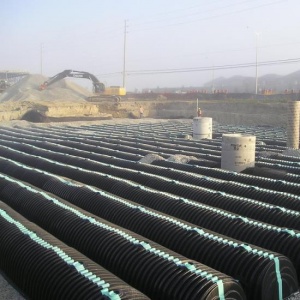
Infiltration chambers being installed.
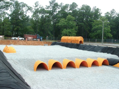
Chamber systems can be very large, both in terms of depth and footprint...
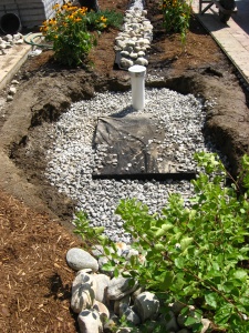
...or very small as this residential soakaway/dry well.

Parking lot stormwater detention system, partially installed. Photo credit: Arbitrarily0

Contractors construct an underground soakaway on the runway extension of Taxiway Alpha as shown here Oct. 5, 2012, at RAF Mildenhall, England. Photo credit: Karen Abeyasekere
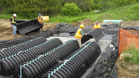
Infiltration chambers being installed.
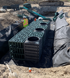
Example of "crate style" Infiltration chambers being installed in East Gwillimbury. Photo credit: Make-Way Environmental Technologies Inc.


External links[edit]
In our effort to make this guide as functional as possible, we have decided to include proprietary systems and links to manufacturers websites.
Inclusion of such links does not constitute endorsement by the Sustainable Technologies Evaluation Program.
Lists are ordered alphabetically; link updates are welcomed using the form below.
Plastic chambers[edit]
Concrete chambers[edit]
- ↑ Porosity of Structural Backfill, Tech Sheet #1, Stormtech, Nov 2012, http://www.stormtech.com/download_files/pdf/techsheet1.pdf accessed 16 October 2017
- ↑ 2.0 2.1 2.2 Judge, Aaron, "Measurement of the Hydraulic Conductivity of Gravels Using a Laboratory Permeameter and Silty Sands Using Field Testing with Observation Wells" (2013). Dissertations. 746. http://scholarworks.umass.edu/open_access_dissertations/746