Difference between revisions of "Infiltration: Testing"
| Line 1: | Line 1: | ||
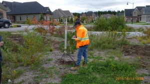
| − | [[File:Infiltration_Testing_1.jpeg|thumb|Infiltration testing at a site in Glen Williams, Ontario]] | + | [[File:Infiltration_Testing_1.jpeg|thumb|Infiltration testing with a Guelph Permeameter at a site in Glen Williams, Ontario]] |
===Four Step Process=== | ===Four Step Process=== | ||
Soil infiltration testing is a four-step process to obtain the necessary information for stormwater management planning and design. The four steps include: | Soil infiltration testing is a four-step process to obtain the necessary information for stormwater management planning and design. The four steps include: | ||
Revision as of 17:23, 20 September 2017
Four Step Process[edit]
Soil infiltration testing is a four-step process to obtain the necessary information for stormwater management planning and design. The four steps include:
1. Background Evaluation
- Based on available published and site specific data;
- Includes consideration of proposed development plan;
- Used to identify potential BMP types, locations and soil test locations;
- Done prior to field work; and
- On-site soil tests may be done to identify/screen potential BMP locations.
2. Test Pit or Soil Boring Observations
- Includes multiple testing locations;
- Provides an understanding of sub-surface conditions; and
- Identifies limiting conditions (e.g., aquitard, bedrock or water table elevations).
3. Infiltration Testing
- Must be conducted on-site;
- Various testing methods are available; and
- Different testing methods for screening versus verification purposes.
4. Design Considerations
- Determination of a suitable infiltration rate for design calculations; and
- Consideration of desired BMP drawdown period.
Background Evaluation[edit]
Prior to performing testing and developing a detailed site plan, existing site conditions should be inventoried and mapped including, but not limited to:
- Surficial geology and underlying stratigraphy;
- Watercourses (perennial and intermittent), water bodies, wetlands and floodplains;
- Small headwater drainage features;
- Topography, slope, and drainage patterns;
- Existing land cover and land use;
- Natural heritage conservation areas; and
- Other man-made features or conditions that may impact design such as existing nearby structures (buildings, infrastructure, etc.).
A sketch plan or preliminary layout plan for the proposed development should be evaluated, including:
- The preliminary grading plan and areas of cut and fill;
- The location and water surface elevation of all existing, and location of proposed water supply sources and wells;
- The location of all existing and proposed on-site wastewater (septic) systems;
- The location of other features of note such as utility rights-of-way, water and sewer lines, etc.;
- Existing data from borehole, well and geophysical testing; and
- Proposed location of development features (buildings, roads, utilities, etc.).
Test Pit or Soil Boring Observations[edit]
Test pits or soil borings provide information regarding the soil horizons and overall soil conditions both horizontally and vertically in that portion of the site. Multiple observations can be made across a site at a relatively low cost and in a short time period.
Test pit excavations or soil borings should extend to a depth of between 2.5 to 5 metres below ground surface or until bedrock or fully saturated conditions are encountered. It is important that the tests provide information related to conditions at least 1.5 metres below the proposed bottom elevation of the infiltration BMP. Test pit trenches should be benched at 1 metre depth intervals for access and infiltration testing.
At each test location, the following conditions should be noted and described:
- Soil horizons (upper and lower boundary);
- Soil texture and colour for each horizon;
- Color patterns (mottling) and observed depth;
- Depth to water table (if encountered);
- Depth to bedrock (if encountered);
- Observations of pores or roots (size, depth);
- Estimated type and percent coarse fragments;
- Hardpan or other limiting layers; and
- Strike and dip of soil horizons.
The number of test pits or soil borings varies depending on site conditions and the proposed development plan. General guidelines are as follows:
- For infiltration BMPs with footprint surface areas from 50 to 900 square metres, a minimum of two test pits or one test pit and two soil borings are required at, or within 10 metres of the proposed location to determine the suitability and distribution of soil types present;
- For infiltration BMPs with footprint surface areas greater than 900 square metres, a minimum of one test should be conducted for each 450 square metres of footprint surface area. Tests should be conducted equidistant from each other to provide adequate characterization of the area;
- For linear infiltration BMPs a minimum of one test should be conducted within each soil mapping unit present along the proposed BMP location. Soil borings should be conducted every 50 metres and a test pit should be conducted every 450 metres; and
- For sites with multiple infiltration BMPs, each with footprint surface areas less than 50 square metres, a minimum of one test pit is required and one soil boring per infiltration BMP location is recommended.
Infiltration Testing[edit]
The preferred testing period is during April and May. If testing is conducted between June 1 and December 1, the soil should be soaked for 24 hours prior, to simulate field saturated conditions.[1]
- If uniform soil texture is observed in the proposed location, at least three percolation test holes should be prepared. If the soil texture changes within the area, make at least two test holes in each soil texture. All test holes should be uniformly spaced across the proposed area.
- Test holes should be between 150 - 200 mm in diameter, and penetrate to the depth of the proposed BMP. Observations should be made on the extracted soil and variations recorded.
- The lowest 300 mm and the bottom of the test pit should be scarified, and the loose material removed.
- A mesh bag containing about 1L of pea gravel may be lowered into the pit, to prevent scouring of the base. Attaching a line to the bag allows it to be removed and reused.
- Carefully pour 6 L of clean water into the base of the pit. A hose is recommended to prevent washing out or erosion of the sides.
- In sandy soils, where half the depth of water percolates within 30 minutes. Otherwise, calculate the infiltration rate
Design Considerations[edit]
The infiltration rate used to design an infiltration BMP must incorporate a safety correction factor that compensates for potential reductions in soil permeability due to compaction or smearing during construction, gradual accumulation of fine sediments over the lifespan of the BMP and uncertainty in measured values when less permeable soil horizons exist within 1.5 metres below the proposed bottom elevation of the BMP.
The measured infiltration rate (in millimetres per hour) at the proposed bottom elevation of the BMP must be divided by a safety correction factor to calculate the design infiltration rate. To select a safety correction factor, calculate the ratio of the mean (geometric) measured infiltration rate at the proposed bottom elevation of the BMP to the rate in the least permeable soil horizon within 1.5 metres below the bottom of the BMP. Based on this ratio, a safety correction factor is selected from the Table below.
For example, where the mean infiltration rate measured at the proposed bottom elevation of the BMP is 30 mm/h, and the mean infiltration rate measured in an underlying soil horizon within 1.5 metres of the bottom is 12 mm/h, the ratio would be 2.5, the safety correction factor would be 3.5, and the design infiltration rate would be 8.6 mm/h. Where the soil horizon is continuous within 1.5 metres below the proposed bottom of the BMP, the mean infiltration rate measured at the bottom elevation of the BMP should be divided by a safety correction factor of 2.5 to calculate the design infiltration rate.
| Ratio of Mean Measured Infiltration Rates | Safety Correction Factor |
|---|---|
| ≤ 1 | 2.5 |
| 1.1 to 4.0 | 3.5 |
| 4.1 to 8.0 | 4.5 |
| 8.1 to 16.0 | 6.5 |
| 16.1 or greater | 8.5 |
- ↑ http://www.extension.umn.edu/environment/housing-technology/moisture-management/how-to-run-a-percolation-test/index.html
- ↑ Wisconsin Department of Natural Resources. 2004. Conservation Practice Standards. Site Evaluation for Stormwater Infiltration (1002). Madison, WI.

