Difference between revisions of "Infiltration: Sizing and modeling"
Jenny Hill (talk | contribs) |
Jenny Hill (talk | contribs) m |
||
| (32 intermediate revisions by the same user not shown) | |||
| Line 1: | Line 1: | ||
__NOTOC__ | __NOTOC__ | ||
| + | <imagemap> | ||
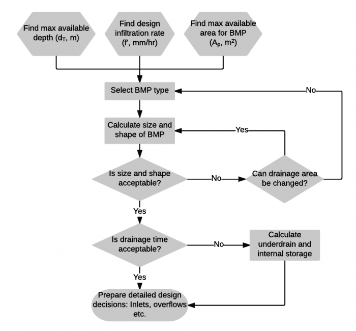
| + | Image:Infiltration.png|thumb|700 px|This is an image map; clicking on components will load the appropriate article. | ||
| + | poly 315 507 208 555 317 605 423 555 [[Drainage time]] | ||
| + | rect 210 658 426 730 [[Details]] | ||
| + | rect 568 522 728 594 [[Underdrain]] | ||
| + | poly 73 27 39 75 75 126 179 126 215 78 181 27 [[Infiltration]] | ||
| + | poly 268 25 235 75 270 123 364 124 395 76 365 25 [[Infiltration: Testing]] | ||
| + | rect 237 185 397 225 [[Select BMP type]] | ||
| + | rect 238 266 397 329 [[Bioretention: Sizing]] | ||
| + | </imagemap> | ||
| + | {{textbox| | ||
| + | {{plainlist| | ||
| + | *To calculate the require depth of an infiltration facility in a specified footprint area... | ||
| + | *To calculate the required footprint area of an infiltration facility with a known depth constraint.... | ||
| + | *To calculate the infiltration time of ponded water on the surface of a facility footprint... | ||
| + | *To calculate the drawdown time of an underground infiltration facility...|}}}} | ||
| + | |||
The sizing calculations require that most of the following parameters be known or estimated. | The sizing calculations require that most of the following parameters be known or estimated. | ||
The exceptions are the depth (''d'') and Permeable area (''P''), as only one of these is required to find the other. | The exceptions are the depth (''d'') and Permeable area (''P''), as only one of these is required to find the other. | ||
Note that some of these parameters are limited: | Note that some of these parameters are limited: | ||
| − | #The ''maximum'' total depth will be limited by construction practices i.e. | + | #The ''maximum'' total depth will be limited by construction practices i.e. usually ≤ 2 m. |
#The ''maximum'' total depth may be limited by the [[Infiltration| conditions underground]] e.g. the groundwater or underlying geology/infrastructure. | #The ''maximum'' total depth may be limited by the [[Infiltration| conditions underground]] e.g. the groundwater or underlying geology/infrastructure. | ||
#The minimum total depth may be limited by the need to support vegetation i.e. not < 0.6 m. | #The minimum total depth may be limited by the need to support vegetation i.e. not < 0.6 m. | ||
#[[Green roofs]], [[absorbent landscapes]] and [[permeable paving]] often receive very little flow from other surfaces, so that the I/P ratio is close to 1. | #[[Green roofs]], [[absorbent landscapes]] and [[permeable paving]] often receive very little flow from other surfaces, so that the I/P ratio is close to 1. | ||
| − | #[[Infiltration trenches]], [[Infiltration chambers| chambers]] and [[bioretention | + | #[[Infiltration trenches]], [[Infiltration chambers| chambers]] and [[bioretention]] have a maximum recommended I/P ratio of 20. |
{|class="wikitable" | {|class="wikitable" | ||
| Line 20: | Line 37: | ||
|''i''||mm/hr||Intensity of design storm (for MOECC volume based calculations use whole storm depth (link to map)) | |''i''||mm/hr||Intensity of design storm (for MOECC volume based calculations use whole storm depth (link to map)) | ||
|- | |- | ||
| − | |''q''||mm/hr||Infiltration coefficient, calculated from measured [[Infiltration: Testing| infiltration rate]] and applied [[Infiltration|safety factor]] | + | |''q''||mm/hr||Infiltration coefficient of the underlying native soil, calculated from measured [[Infiltration: Testing| infiltration rate]] and applied [[Infiltration|safety factor]] |
|- | |- | ||
|''n''||-||Porosity, as measured (or default to 0.35 for all aggregates).<br> *Note: For systems that have significant storage in clear open chambers, an effective porosity value (''n<nowiki>'</nowiki>'') may be estimated for the whole installation and used in the calculations below. Effective porosity will vary according to the geometry of the storage chambers, so advice should be sought from product manufacturers. Permit applications should include the basis for ''n<nowiki>'</nowiki>'' estimates. | |''n''||-||Porosity, as measured (or default to 0.35 for all aggregates).<br> *Note: For systems that have significant storage in clear open chambers, an effective porosity value (''n<nowiki>'</nowiki>'') may be estimated for the whole installation and used in the calculations below. Effective porosity will vary according to the geometry of the storage chambers, so advice should be sought from product manufacturers. Permit applications should include the basis for ''n<nowiki>'</nowiki>'' estimates. | ||
| Line 29: | Line 46: | ||
|- | |- | ||
|''P''||m<sup>2</sup>||Permeable area i.e. footprint area of the facility or BMP | |''P''||m<sup>2</sup>||Permeable area i.e. footprint area of the facility or BMP | ||
| + | |- | ||
| + | |''K''||mm/hr||Infiltration coefficient of the filter media or fill used in the infiltration facility | ||
|} | |} | ||
| Line 34: | Line 53: | ||
{{Clickable button|[[Media:Infiltration Sizing.xlsx|Download .xlsx calculation tool]]}} | {{Clickable button|[[Media:Infiltration Sizing.xlsx|Download .xlsx calculation tool]]}} | ||
| − | == | + | ==To calculate the required depth, where the area of the facility is constrained (3D)== |
| − | The | + | In some very constrained sites, the surface area of the BMP may be limited, in this case the required depth of cell or trench can be calculated: |
| − | + | :<math>d=a[e^{\left ( -bD \right )} -1]</math> | |
| + | Where | ||
| + | <math>a=\frac{P}{x}-\frac{i I}{P q}</math> | ||
| + | and | ||
| + | <math>b=\frac{xq}{nP}</math> | ||
| + | |||
| + | (The rearrangement to calculate the required footprint area of the facility for a given depth using three dimensions of underground infiltration is not available at this time. Elegant submissions are invited.) | ||
| − | To calculate the required depth, where the area of the facility is constrained: | + | ==To calculate the required depth, where the area of the facility is constrained (1D)== |
| − | <math>d=\frac{D\left[\left( \frac{I}{P} \right )i-q \right]}{n}</math> | + | In some very constrained sites, the surface area of the BMP may be limited, in this case the required depth of cell or trench can be calculated. |
| + | Note that in most cases the results of this calculation will be very similar to those of the above equation using 3D infiltration. | ||
| + | :<math>d=\frac{D\left[\left( \frac{I}{P} \right )i-q \right]}{n}</math> | ||
| − | To calculate the require facility area or footprint where the depth is constrained: | + | ==To calculate the require facility area or footprint where the depth is constrained (1D)== |
| + | In many locations throughout Ontario, there may be limited depth of soil available into which stormwater may be infiltrated. In this case the required storage needs to be distributed more widely across the landscape. The overall are of BMP required can be calculated: | ||
<math>P=\frac{IiD}{nd+qD}</math> | <math>P=\frac{IiD}{nd+qD}</math> | ||
| − | + | ==Time for infiltration of surface ponded water== | |
| − | The | + | The following equation assumes that infiltration occurs primarily through the footprint of the facility. |
| − | To calculate the time (''t'') to fully drain the facility: | + | It is best applied to calculate the limited duration ponding on the surface of [[bioretention cells]], [[bioswales]] and [[enhanced grass swales]]. |
| − | <math>t=\frac{ | + | To calculate the time (''t'') to fully drain the facility through the footprint area only: |
| + | <math>t=\frac{d}{K}</math> | ||
| − | == | + | ==Drawdown time to empty facility== |
[[file:Hydraulic radius.png|thumb|Three footprint areas of 9 m<sup>2</sup>.<br> | [[file:Hydraulic radius.png|thumb|Three footprint areas of 9 m<sup>2</sup>.<br> | ||
From left to right x = 12 m, x = 14 m, and x = 16 m]] | From left to right x = 12 m, x = 14 m, and x = 16 m]] | ||
| − | For some geometries (e.g. particularly deep facilities or linear facilities), it | + | The target [[drawdown time]] for the internal storage of an infiltration facility is between 48-72 hours. <br> |
| − | The | + | For some geometries (e.g. particularly deep facilities or linear facilities), it preferable to account for lateral infiltration. |
| − | Maximizing the perimeter of the facility directs designers towards longer, linear shapes such as [[infiltration trenches]] and [[bioswales]]. | + | The 3D equation make use of the hydraulic radius (''P''/''x''), where ''x'' is the perimeter (m) of the facility. <br> |
| − | + | '''Maximizing the perimeter of the facility directs designers towards longer, linear shapes such as [[infiltration trenches]] and [[bioswales]].''' | |
| − | |||
| − | |||
| − | |||
| − | |||
| − | |||
| − | |||
| − | |||
| − | |||
| − | |||
| − | |||
| − | |||
To calculate the time (''t'') to fully drain the facility: | To calculate the time (''t'') to fully drain the facility: | ||
<math>t=\frac{nP}{qx}ln\left [ \frac{\left (d+ \frac{P}{x} \right )}{\left(\frac{P}{x}\right)}\right]</math> | <math>t=\frac{nP}{qx}ln\left [ \frac{\left (d+ \frac{P}{x} \right )}{\left(\frac{P}{x}\right)}\right]</math> | ||
Revision as of 00:15, 22 March 2018
- To calculate the require depth of an infiltration facility in a specified footprint area...
- To calculate the required footprint area of an infiltration facility with a known depth constraint....
- To calculate the infiltration time of ponded water on the surface of a facility footprint...
- To calculate the drawdown time of an underground infiltration facility...
The sizing calculations require that most of the following parameters be known or estimated. The exceptions are the depth (d) and Permeable area (P), as only one of these is required to find the other. Note that some of these parameters are limited:
- The maximum total depth will be limited by construction practices i.e. usually ≤ 2 m.
- The maximum total depth may be limited by the conditions underground e.g. the groundwater or underlying geology/infrastructure.
- The minimum total depth may be limited by the need to support vegetation i.e. not < 0.6 m.
- Green roofs, absorbent landscapes and permeable paving often receive very little flow from other surfaces, so that the I/P ratio is close to 1.
- Infiltration trenches, chambers and bioretention have a maximum recommended I/P ratio of 20.
| Symbol | Units | Parameter |
|---|---|---|
| D | hrs | Duration of design storm (for MOECC volume based caclulations set to 1) |
| i | mm/hr | Intensity of design storm (for MOECC volume based calculations use whole storm depth (link to map)) |
| q | mm/hr | Infiltration coefficient of the underlying native soil, calculated from measured infiltration rate and applied safety factor |
| n | - | Porosity, as measured (or default to 0.35 for all aggregates). *Note: For systems that have significant storage in clear open chambers, an effective porosity value (n') may be estimated for the whole installation and used in the calculations below. Effective porosity will vary according to the geometry of the storage chambers, so advice should be sought from product manufacturers. Permit applications should include the basis for n' estimates. |
| I | m2 | Impermeable area i.e. catchment |
| d | m | depth of infiltration facility or BMP |
| P | m2 | Permeable area i.e. footprint area of the facility or BMP |
| K | mm/hr | Infiltration coefficient of the filter media or fill used in the infiltration facility |
This spreadsheet tool has been set up to perform all of the calculations shown below
To calculate the required depth, where the area of the facility is constrained (3D)[edit]
In some very constrained sites, the surface area of the BMP may be limited, in this case the required depth of cell or trench can be calculated:
![{\displaystyle d=a[e^{\left(-bD\right)}-1]}](https://wikimedia.org/api/rest_v1/media/math/render/svg/8b7aff54e8cdb29929df7ac7ee3815c6bb830270)
Where and


(The rearrangement to calculate the required footprint area of the facility for a given depth using three dimensions of underground infiltration is not available at this time. Elegant submissions are invited.)
To calculate the required depth, where the area of the facility is constrained (1D)[edit]
In some very constrained sites, the surface area of the BMP may be limited, in this case the required depth of cell or trench can be calculated. Note that in most cases the results of this calculation will be very similar to those of the above equation using 3D infiltration.
![{\displaystyle d={\frac {D\left[\left({\frac {I}{P}}\right)i-q\right]}{n}}}](https://wikimedia.org/api/rest_v1/media/math/render/svg/5fd867b2785416138e5925a5c4b084dee932a19b)
To calculate the require facility area or footprint where the depth is constrained (1D)[edit]
In many locations throughout Ontario, there may be limited depth of soil available into which stormwater may be infiltrated. In this case the required storage needs to be distributed more widely across the landscape. The overall are of BMP required can be calculated:

Time for infiltration of surface ponded water[edit]
The following equation assumes that infiltration occurs primarily through the footprint of the facility. It is best applied to calculate the limited duration ponding on the surface of bioretention cells, bioswales and enhanced grass swales. To calculate the time (t) to fully drain the facility through the footprint area only:

Drawdown time to empty facility[edit]

The target drawdown time for the internal storage of an infiltration facility is between 48-72 hours.
For some geometries (e.g. particularly deep facilities or linear facilities), it preferable to account for lateral infiltration.
The 3D equation make use of the hydraulic radius (P/x), where x is the perimeter (m) of the facility.
Maximizing the perimeter of the facility directs designers towards longer, linear shapes such as infiltration trenches and bioswales.
To calculate the time (t) to fully drain the facility:
![{\displaystyle t={\frac {nP}{qx}}ln\left[{\frac {\left(d+{\frac {P}{x}}\right)}{\left({\frac {P}{x}}\right)}}\right]}](https://wikimedia.org/api/rest_v1/media/math/render/svg/2b7bfbb66a01773d9a1cb2da0ad1fa1380792212)