Finishing grades and surface layer installation: permeable pavements

Overview[edit]
This section gives guidance for project managers, engineers, and contractors on the finishing grades and surface layer installation steps required for successful construction of permeable pavements.
Bedding layer[edit]

The bedding layer consists of a coarse stone and provides a level medium onto which paved surfaces are installed. Note that bedding layers are required for permeable pavers but not porous concrete. Additionally, the bedding layer can function as the choker layer, depending on the design.
Construction Steps:
- Place stone bedding material on top of compacted reservoir course.
- Level aggregate to the appropriate depth, as per the design. A vibratory screed can be used to level the bedding material.
Key Inspection Points:
- Granular bedding material is correct size and material (e.g. 5 mm stone) upon arrival to site. For an example of a municipal standard for gradation and material size, refer to (City of Toronto, 2021)[1].
- Bedding depth conforms to design and is uniform across the LID feature.
- When a 3-metre straightedge is placed on the surface of the bedding material, gaps between the straightedge and bedding surface are not greater than 10 mm at any point.
Mistakes to Avoid:
- Fines in the aggregate – ensure that the correct stone gradation is provided and the medium is free of fines and crushed stone. See Jar test to ensure there are no fines in the crushed stone aggregate.
- Compaction – the bedding layer cannot be compacted
- Use of plate vibrators – do not use plate vibrators for levelling, as they can crush the bedding material. Tamping should be performed after the installation of the pavers.
For more guidance on materials specifications, refer to Aggregates, OPSS aggregates and (Ontario Provincial Standards, 2013) [2]
Placement and finishing[edit]


The installation of pervious concrete requires the placement of ready-mix into forms. Unlike permeable pavers, pervious concrete also requires extensive curing time. Pervious concrete has the most particular installation requirements of the various permeable pavement types. It is recommended that contractors with certifications for the installation of pervious concrete, such as National Ready Mix Concrete Association certifications (NRMCA, 2022)[5] are tasked with its installation. See Permeable pavements: Specifications for more information.
Construction Steps:
- Install 10 mm vertical spacers on the forms.
- Dampen the sub-base prior to the placement of pervious concrete with a pressure mister. Doing so helps to avoid interfering with the dry mix’s critical moisture content.
- Direct concrete from the chute of the ready-mix truck onto the subbase.
- Pre-level the ready mix with rakes.
- Consolidate the concrete with a vibratory screed. The vibratory screed maintains the void space needed for hydrologic performance. This is the initial consolidation.
- Apply moisture to the surface of the newly poured concrete with a pressure mister.
- Remove 10 mm vertical spacers and compact the concrete surface with a hand roller. A 30-cm piece of 4” PVC that is filled with water is recommended for hand rolling. This is final compaction.
- Hand-tamp the edges of the form.
- Within 15 minutes of placement, cover the concrete surface with a 6-mm sheet of white plastic.
- Keep the concrete covered for 7 days without any traffic.
- Remove the plastic once curing is complete.
Note: Throughout the process of pouring concrete, the moisture content of the ready mix should be periodically adjusted to meet specification.
Key Inspection Points:
- Climate conditions are acceptable for placement. Ideal conditions include the following:
- Temperature of about 15°C
- Overcast weather
- Little or no wind
- Some humidity
- Moisture of ready mix is certified by an expert or product representative prior to placement.
- Subbase is wetted prior to placement to avoid having moisture drawn out of the concrete by the underlaying material.
- Forms are wide enough to support the vibratory screed.
- Surface of consolidated concrete is wetted prior to laying down plastic cover to avoid sticking.
- Plastic cover is white to reduce the solar load on the pavement.
- Concrete can be formed into a ball, roughly sized as a softball, in one’s hand without falling apart.
- Concrete placement is certified by a product representative.
- Wash-out areas are provided for concrete trucks and other equipment.
Mistakes to Avoid:
- Delivery of excessively wet ready-mix - It is easier to receive ready mix that is on the dry side and add moisture than it is to dry it out. Excess moisture can result in glazing and placing excessively dry concrete can result in raveling.
- Adding moisture with a hose – do not use the hose from the ready-mix truck to add moisture to the subbase or concrete surface. This will separate the rock and cement base of the concrete, resulting in excessive raveling. Only a pressure mister should be used.
- Unacceptable weather conditions – concrete can fail to cure properly if ambient conditions are unsuitable.
- Weighing down plastic – do not weigh down the plastic cover with dirt or other material. Dirt and other materials can fill the voids of the concrete. Instead, plastic can be secured in place at the sides of the LID practice.
- Designated wash-out stations – do not wash concrete trucks and other heavy equipment in or near the infiltration area.
- Insufficient covering time – some raveling will always occur when placing concrete, but raveling can be minimized by ensuring proper covering time.
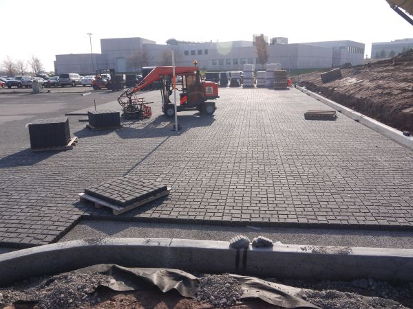
Paver installation[edit]
Permeable pavers have the highest load tolerance of the permeable pavement variations. It is especially important that the permeable pavers be installed correctly on the bedding material. See Permeable pavements: Specifications for more information.
Construction Steps:
- Lay permeable pavers by hand or install whole pallets of pavers at a time with specialized equipment.
- Cut pavers to fit into the edges of the infiltration area.
- Fill voids between pavers with joint aggregate.
- Sweep excess joint aggregate from pavement surface.
- Compact completed surfaces with a plate vibrator at the end of each day or when all pavers are placed. The plate vibrator can be applied up to 1.8 m from the laying face (incomplete edge).
Key Inspection Points:
- Cracked/broken pavers are discarded and replaced with intact pavers prior to filling void spaces.
- Sizes of pavers and joint width conform to applicable municipal standards.
- Pavers conform to the specifications of the design.
- Minimum setback of 1.8 m from the laying face is considered when compacting at the end of each workday.
- Cut pavers are installed to edges of the practice before compaction of completed sections takes place.
- Pavers are elevated within 3 mm to 10 mm above adjacent inlets or channels.
- Paver pattern and joint widths conform to the directions of the manufacturer.
- Permeable pavers are compacted at least twice with a plate compactor.
Mistakes to Avoid:
- Leaving pavers uncompacted – finished surfaces must be compacted at the end of each workday.
- Cutting blocks in infiltration area – edge pavers should be cut with a wet saw in a designated area away from the infiltration area to avoid clogging with fines and dust.
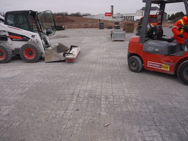
Installing entire pallets of pavers is possible with specialized equipment. (Photo Source: CVC, 2012)
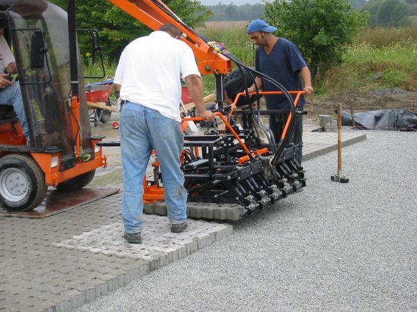
The equipment shown can install single pallets of pavers all at once. (Photo Source: TRCA, n.d.)
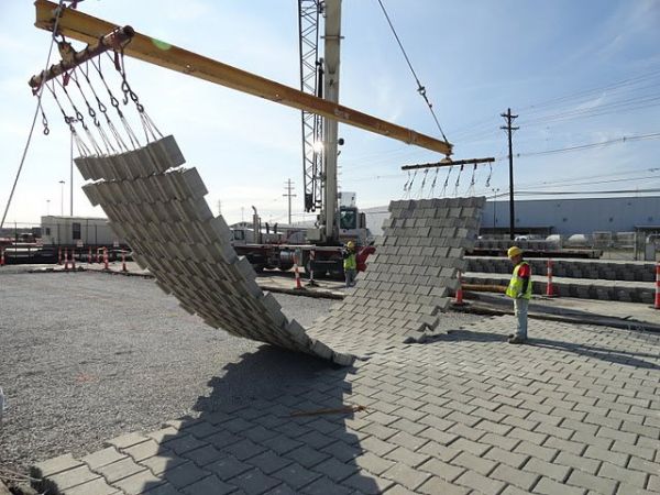
Joined permeable pavers being installed with a crane. (Photo Source: TRCA, n.d.)
Pavers cut to the shape of the adjacent curb at IMAX Headquarters in Mississauga. (Photo Source: CVC, 2013)
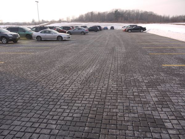
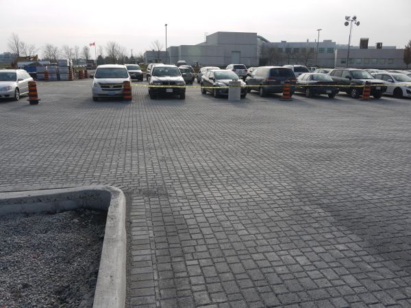
Finished parking lot at IMAX Headquarters in Mississauga. (Photo Source: CVC, 2013)
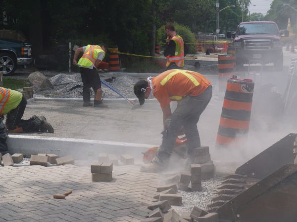
Cutting pavers within the infiltration area is not advised as the fines/dust could clog the permeable surface. (Photo Source: CVC, 2014)


Tamping[edit]
Tamping is an important construction step when installing permeable pavements systems. Tamping allows for the permeable surface (concrete or pavers) to set and adhere to the bedding layer beneath. Tamping also allows for flattening or evening out the surface, resulting in visually appealing finish.
Construction Steps:
- Remove any pieces that have imperfections on the surface.
- Place the tamper onto the pavement surface.
- Pass the tamper across all the pavement area.
Key Inspection Points:
- Equipment: According to the (City of Edmonton, 2016)[6], tamp the permeable surface with a "low amplitude plate vibrator (22-kN) compaction force at 75 to 95 Hz".
Mistakes to Avoid:
- Pervious Concrete
- Delays in tamping the pervious concrete. Tamping should be completed no more than 15 minutes after the concrete was placed.
- Permeable Interlocking Concrete Pavers
- Forgetting to place a rubber pad attachment beneath the metal tamper plate. If no rubber mat is used the tamper may damage the surface of the pavers.

Tamping of Permeable Interlocking Concrete Pavement units after being placed on-site.
(This Old House, 2022)[7]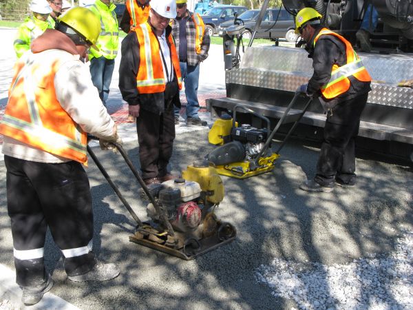
Tamping of permeable concrete at TRCA's head office in Vaughn, Ontario.
(Photo source: TRCA, 2009)


Joint cutting[edit]

Pavement joints are important in permeable concrete systems to prevent the pavement being cracked and moved. These potential problems are caused by water, ice, salt and loads on the pavement surface.
Construction Steps:
- Ensure joint pattern and width match drawing details. According to the (American Concrete Institute (ACI), 2013)[9], “minimum joint width for saw cutting is 3 mm”.
- Cut the joints on the pervious concrete surface immediately after the concrete is rolled/compacted.
- Alternatively, sawcut concrete after concrete has solidified enough to avoid removing aggregate material from the concrete pavement.
Key Inspection Points:
- Use of appropriate equipment
- Right width and depth
Joint aggregate[edit]
The joint aggregate is an important component of Permeable Interlocking Concrete Pavement (PICP) installations, as it allows for water falling on the surface to infiltrate into the underlying layers (bedding and filter layer, base course, and sub-base reservoir).
Construction Steps:
- Ensure paver pattern and joint width match drawing details.
- Fill in the openings and joints with ASTM No. 8 stone ( mm)* using tools such as a brush or a broom.
- Sweep the pavers to remove excess aggregate on the surface.
- Apply additional aggregate to the openings and joints, filling them completely.
- Repeat steps 4-5 until the joint gap has been filled completely.
Note: Some paver joint widths may be narrow and not accept most of the ASTM No. 8 stone - (Interlocking Concrete Pavement Magazine, 2007)[10]. Instead, use material that will fill the joints such as washed ASTM No. 9( mm) or No. 10 (mm) stone.
Key Inspection Points:
- Material arrival: Ensure that material meets specifications and is free of debris and fines.
- Material installation: Ensure that material is being placed with proper equipment (brush/broom).
Mistakes to Avoid:
- Accept material that does not meets design specifications.
- Accept material that contains fines or debris.
- Do not tamp vibrate material into joint
Joint material being swept with a brush to fill in the joint space.
(Photo source: CVC)
Final appearance of the joint material in the permeable interlocking concrete pavement system.
(Photo source: CVC)


Curbing[edit]

It is very important to make sure that the contractor responsible for curb construction understands curb cut designs and elevations. This is often a new technique for contractors, and they may not understand the overall concept of water in the gutter line being directed behind the gutter.
Construction Steps:
- Place the right forms (rolled curve vs standard) in the inlet location.
- Pour concrete.
- Shape the inlet
- Add the river stone on top of the fresh concrete (if applicable)
- Provide sufficient curing time, according to (CSA, 2009)[11]

Key Inspection Points:
- Use of proper curb form by sub-contractor.
- Curb type aligns with design.
- Curb cut location, type and dimension aligns with design.
- Designated concrete wash out is in place and away from LID facility.
Mistakes to Avoid:
- Elevated curb cuts and reverse slopes (sloping from back of curb towards instead of depressing from gutter line towards the back).
- Wrong curb cut width size.
- Use of wrong curb form.
- Concrete wash out within or upstream of LID facility.
- Ensure curb granular base (granular A) does not spill over into LID infiltration area. If material spills over, remove as best as possible while still maintaining the 2:1 slope for curbing
- Lack of communication to concrete contractor or ready-mix driver explaining the function and importance of protecting the LID feature.
For more information on curb cuts, see these pages: Curb cuts, Curb cuts: Gallery and Bioretention: Streetscapes

Stabilizing contributing drainage area[edit]
Similar to the plant material verification and installation task shown above, any planting required to stabilize the contributing drainage area will need to meet the specifications and considerations shown above.
Additionally, if turf/grass is required to stabilize the contributing drainage area, installation should be done as per the grower/nursery’s specifications and standards. See turf reinforcement for more information.
As-built surveys[edit]
Throughout the construction process, it is sometimes necessary to deviate from the intended design of LID features and adapt the design to on-site conditions. The completion of a post-construction as-built survey is a standard operating procedure for engineering projects that captures any changes made to the feature’s design during construction. For an example of municipal standards for as-built surveys, refer to the City of Toronto's Engineering Survey Standards for Consultants[12]
Survey Steps:
- Use the same datum as the pre-engineering survey.
- If a pre-engineering survey is not available, use a reference feature as the datum.
- Identify the type, diameter, and material of exposed utilities.
- Include data on critical feature elevations and existing utilities, such as:
- Inverts of newly installed pipe
- Vertical and horizontal bends in pipes
- Existing public utilities
- Existing private utilities
- New and existing structures (e.g., catchbasins, manholes, chambers, etc.)
Inspection Points:
- Datum matches the pre-engineering survey or selected reference feature.
- Data provided in as-built survey matches the as-built standards of the local municipality.
References[edit]
- ↑ City of Toronto. 2021. TS 861 Construction Specifications for Permeable Interlocking Concrete Pavers. https://www.toronto.ca/wp-content/uploads/2021/08/952c-ecs-specs-gi-specs-TS861Sep2021.pdf
- ↑ Ontario Provincial Standards. 2013. OPSS.PROV.10101 Aggregates - Base, Subbase Select Subgrade, and Backfill Material. https://www.roadauthority.com/Standards/?id=a28fdfaf-3bf8-4679-81ca-4e44b2263cf8
- ↑ CVC. 2012. Low Impact Development Construction Guide. Version 1.0. https://cvc.ca/wp-content/uploads/2013/03/CVC-LID-Construction-Guide-Book.pdf
- ↑ Washington State Department of Transportation on Flickr. 2011. Summer construction on the Salmon Creek Interchange Project. https://www.flickr.com/photos/wsdot/6170651056
- ↑ National Ready Mix Concrete Association. 2022. Certifications https://www.nrmca.org/certifications/
- ↑ City of Edmonton. 2016. Low Impact Development Construction, Inspection & Maintenance Guide. Edition 1.0. https://www.edmonton.ca/public-files/assets/document?path=LID%20CIM%20Guide.pdf
- ↑ This Old House. 2022. How to Install a Permeable-Paver Driveway. Photo. Accessed August 2022. https://www.thisoldhouse.com/driveways/21016426/how-to-install-a-permeable-paver-driveway
- ↑ Concrete Network. 2022. Permeable Concrete Pavements. Photo. Accessed August 13 2022. https://www.concretenetwork.com/pervious/
- ↑ ACI. 2013. ACI 522.1-13 Specification for Pervious Concrete Pavement https://www.concrete.org/store/productdetail.aspx?ItemID=5221U13&Format=PROTECTED_PDF&Language=English&Units=US_Units
- ↑ Interlocking Concrete Pavement Magazine. 2017. Contractor Focus: Construction of Bases for Permeable Interlocking Concrete Pavements - Part I. Edition August 2007. https://www.angeluspavingstones.com/wp-content/uploads/2012/11/07_Aug_Contractor_Focus.pdf
- ↑ CSA. 2009. A23.1-09/A23.2-09 (R2014). Concrete materials and methods of concrete construction/Test methods and standard practices for concrete. standard A23.1-09. https://www.csagroup.org/store/product/2420232/#:~:text=and%20specialty%20concretes.-,A23.,A%20sister%20standard%20%E2%80%93%20CSA%20A23
- ↑ City of Toronto. 2021. Engineering Survey Standards for Consultants. https://www.toronto.ca/wp-content/uploads/2017/11/98c7-ecs-specs-surveys-engsrv_survey_standards_for_consultant.pdf