Difference between revisions of "Exfiltration trenches"
| (2 intermediate revisions by the same user not shown) | |||
| Line 12: | Line 12: | ||
| − | Exfiltration trenches are similar to [[infiltration trenches]] but differ primarily | + | Exfiltration trenches are similar to [[infiltration trenches]] but differ primarily inthe manner in which stormwater is delivered to the trench.<br> |
Runoff enters infiltration trenches directly by infiltration from the surface. In exfiltration systems, surface runoff is collected by drainage [[inlets]] and delivered to the trench via subsurface perforated [[pipes]]. | Runoff enters infiltration trenches directly by infiltration from the surface. In exfiltration systems, surface runoff is collected by drainage [[inlets]] and delivered to the trench via subsurface perforated [[pipes]]. | ||
{{TOClimit|2}} | {{TOClimit|2}} | ||
| Line 71: | Line 71: | ||
===Drawings=== | ===Drawings=== | ||
Standard details for exfiltration trenches have been produced by City of Kitchener and City of Barrie. See [[Drawings]] | Standard details for exfiltration trenches have been produced by City of Kitchener and City of Barrie. See [[Drawings]] | ||
| + | |||
| + | ==Inspection and Maintenance== | ||
| + | Routine inspection and maintenance consists of checking and cleaning trash, debris and sediment from [[pretreatment]] devices, [[inlets]] and [[overflow|outlets]] twice a year in the spring and/or late fall, or when pretreatment device sump is half full. Use hydro-vac truck to remove sediment from catch basin sumps, [[OGS]] and isolated chamber row filter pre-treatment devices. To clean isolated chamber row filters use a vacuum truck equipped with rear-facing jet nozzle for cleaning large diameter pipes or culverts. | ||
| + | |||
| + | Monitoring of storage reservoir water level during and after natural or simulated storm events using the monitoring well should be performed periodically to verify the facility drains within the required drainage time (typically 72 hours). Should be performed as part of inspections following construction or major rehabilitation prior to assumption, and every 15 years at a minimum, to track drainage performance over time and determine when replacement is needed. <br> | ||
| + | </br> | ||
| + | Take a look at the [[Inspection and Maintenance: Underground Infiltration Systems]] page by clicking below for further details about proper inspection and maintenance practices: | ||
| + | |||
| + | {{Clickable button|[[File:Cover page underground.PNG|150px|link=https://wiki.sustainabletechnologies.ca/wiki/Inspection_and_Maintenance:_Underground_Infiltration_System]]}} | ||
| + | |||
==Gallery== | ==Gallery== | ||
{{:Exfiltration:_Gallery}} | {{:Exfiltration:_Gallery}} | ||
Revision as of 16:21, 10 March 2023
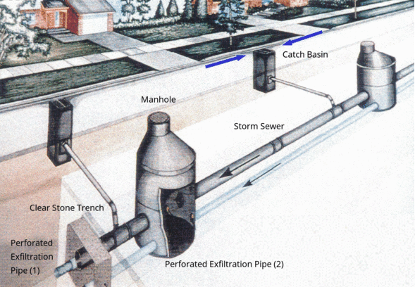
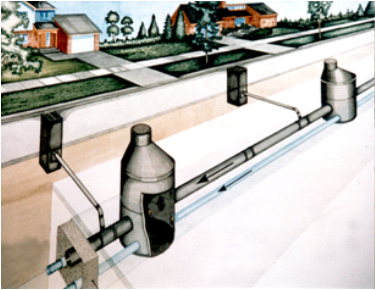
Exfiltration trenches are similar to infiltration trenches but differ primarily inthe manner in which stormwater is delivered to the trench.
Runoff enters infiltration trenches directly by infiltration from the surface. In exfiltration systems, surface runoff is collected by drainage inlets and delivered to the trench via subsurface perforated pipes.
Overview[edit]
Exfiltration systems can be thought of as infiltration trenches that are integrated with conventional stormwater conveyance systems (i.e. catch basins, solid pipes and maintenance holes), designed for both conveyance and infiltration of excess stormwater. By attenuating runoff volume, they reduce contaminant loads delivered to downstream BMPs, end-of-pipe facilities or receiving waterbodies.
Exfiltration pipe systems are an ideal technology for:
- Road retrofits where sewer lines are being replaced,
- All new road/storm sewer constructions where no constraints to infiltration exist,
- Tight urban spaces where no landscaped practices can be squeezed in, and there is a low risk tolerance for flooding.

Take a look at the downloadable Exfiltration Trench Systems Factsheet below for a .pdf overview of this LID Best Management Practice:

The fundamental components of an exfiltration system are:
- pre-treatment devices to retain coarse sediment, trash, debris and floatables,
- perforated pipes embedded in washed gravel connected to maintenance holes and catch basins,
- a gently sloping granular storage reservoir below the perforated pipe.
Optional components include:
- Geotextile to prevent migration of fines into the reservoir;
- Trench plugs to help disperse stormwater throughout the trench and enhance infiltration; and
- Perforated maintenance hole or catch basin risers.
Exfiltration systems can be used in place of conventional storm sewer pipes, where topography, water table depth, and water quality conditions are suitable. They are suitable for treating runoff from roofs, walkways, parking lots and low to medium traffic roads, with adequate pretreatment. Exfiltration systems can also be referred to as perforated pipe systems, clean water collector systems and percolation drainage systems.
Planning[edit]
If properly located, designed and maintained, perforated pipe systems can greatly reduce runoff volume while having little or no surface footprint, which helps to conserve highly valued developable land.
Systems should be located below shoulders of roadways, permeable pavements or swales where they can be readily excavated for servicing. An adequate subsurface area outside of the 4 m setback from building foundations and suitable distance from other underground utilities must be available.
Infiltration[edit]
For information about constraints to infiltration practices, and approaches and tools for identifying and designing within them see Infiltration.
Native Soil[edit]
Exfiltration trench systems can be constructed over any soil type, but hydrologic soil group (HSG) A or B soils are best for achieving water balance and erosion control objectives. Facilities should be located on portions of the site with the highest infiltration rates. Native soil infiltration rate at the proposed facility location and depth should be confirmed through in-situ measurements of hydraulic conductivity under field saturated conditions. For guidance on infiltration testing and selecting a design infiltration rate see Design infiltration rate.
Site Topography[edit]
Systems cannot be located on natural slopes > 15 %.
For more information on planning considerations and site constraints see Infiltration trenches.
For a table summarizing information on planning considerations and site constraints see Site considerations.
Design[edit]
Geometry and Site Layout[edit]
- Gravel beds in which exfiltration systems are installed are typically rectangular excavations with a bottom width between 0.6 and 2.4 m [1].
- The gravel beds should have gentle slopes between 0.5 - 1 %.
- Calculate maximum flow through perforated pipe
Drawings[edit]
Standard details for exfiltration trenches have been produced by City of Kitchener and City of Barrie. See Drawings
Inspection and Maintenance[edit]
Routine inspection and maintenance consists of checking and cleaning trash, debris and sediment from pretreatment devices, inlets and outlets twice a year in the spring and/or late fall, or when pretreatment device sump is half full. Use hydro-vac truck to remove sediment from catch basin sumps, OGS and isolated chamber row filter pre-treatment devices. To clean isolated chamber row filters use a vacuum truck equipped with rear-facing jet nozzle for cleaning large diameter pipes or culverts.
Monitoring of storage reservoir water level during and after natural or simulated storm events using the monitoring well should be performed periodically to verify the facility drains within the required drainage time (typically 72 hours). Should be performed as part of inspections following construction or major rehabilitation prior to assumption, and every 15 years at a minimum, to track drainage performance over time and determine when replacement is needed.
Take a look at the Inspection and Maintenance: Underground Infiltration Systems page by clicking below for further details about proper inspection and maintenance practices:

Gallery[edit]
The 'Etobicoke Exfiltration system' (1994), Etobicoke ON
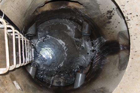
A pair of perforated pipes can be seen in this manhole during cleaning operations. Four connections in total as this manhole is part-way along the system.


Materials[edit]
This article gives recommendations for aggregate to be used to store water for infiltration. This is usually called 'clear stone' at aggregate yards.
To see an analysis of Ontario Standard Specifications for granular materials, see OPSS aggregates.
For advice on decorative surface aggregates see Stone
Gravel used for underdrains in bioretention, infiltration trenches and chambers, and exfiltration trenches should be 20 or 50 mm, uniformly-graded, clean (maximum wash loss of 0.5%), crushed angular stone that has a porosity of 0.4[2].
The clean wash to prevent rapid accumulation of fines from the aggregate particles in the base of the reservoir. The uniform grading and the angularity are important to maintain pore throats and clear voids between particles. (i.e. achieve the porosity). Porosity and permeability are directly influenced by the size, gradation and angularity of the particles [3]. See jar test for on-site verification testing protocols.
Gravel with structural requirements should also meet the following criteria:
- Minimum durability index of 35
- Maximum abrasion of 10% for 100 revolutions and maximum of 50% for 500 revolutions
Standard specifications for the gradation of aggregates are maintained by ASTM D2940
The highest porosity is found in uniformly graded aggregate, as there are no smaller particles to occupy the inter-particle pores. [3]
Higher permeability is found in larger, angular, uniformly graded aggregate. This is due to larger pore sizes and lower tortuosity. [3]


See Clogging for notes on their application in LID structures.
Geotextiles can be used to prevent downward migration of smaller particles in to larger aggregates, and slump of heavier particles into finer underlying courses. Geotextiles are commonly used on low strength soils (CBR<4). The formation of biofilm on geotextiles has also been shown to improve water quality:
- By degrading petroleum hydrocarbons[4]
- By reducing organic pollutant and nutrient concentrations [5]
- When installing geotextiles an overlap of 150 - 300 mm should be used.
Material specifications should conform to OPSS 1860 for Class II geotextile fabrics [6]. Note when expansive clays are present, a non-infiltrating design may be necessary. If used, geotextile socks around perforated pipes should conform to ASTM D6707 with minimum water flow rate conforming to ASTM D4491 (12,263 L/min/m2 at 5 cm head).
- Fabrics should be woven monofilament or non-woven needle punched.
- Woven slit film and non-woven heat bonded fabrics should not be used, as they are prone to clogging.
In choosing a product, consider:
- The maximum forces that will be exerted on the fabric (i.e., what tensile, tear and puncture strength ratings are required?),
- The load bearing ratio of the underlying native soil (i.e. is the geotextile needed to prevent downward migration of aggregate into the native soil?),
- The texture (i.e., grain size distribution) of the overlying and underlying materials, and
- The suitable apparent opening size (AOS) for non-woven fabrics, or percent open area (POA) for woven fabrics, to maintain water flow even with sediment and microbial film build-up.
| Percent soil/filter media passing 0.075 mm (#200 sieve) | Non-woven fabric apparent opening size (AOS, mm) | Woven fabric percent open area (POA, %) | Permittivity (sec-1) |
|---|---|---|---|
| >85 | ≤ 0.3 | - | 0.1 |
| 50 - 85 | ≤ 0.3 | ≥ 4 | 0.1 |
| 15 - 50 | ≤ 0.6 | ≥ 4 | 0.2 |
| 5 - 15 | ≤ 0.6 | ≥ 4 | 0.5 |
| ≤ 5 | ≤ 0.6 | ≥ 10 | 0.5 |
Performance research[edit]
http://www.mdpi.com/2073-4441/7/4/1595/htm
Performance[edit]
| Water balance benefit | Water quality improvement | Erosion control benefit |
|---|---|---|
| Yes | Yes | Partial: depending on soil infiltration rate |
Water balance[edit]
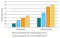
The degree to which water balance objectives are met will depend on the underlying native soil type on which the system is located. Several Ontario studies have assess the performance of exfiltration systems in cold climates.
| Practice | Location | Underlying soil type | Runoff reduction |
|---|---|---|---|
| Grass swale/perforated pipe | Nepean, ON[7] | Silty till | 73 % |
| Grass swale/perforated pipe | Nepean, ON[7] | Sandy silty till | 86 % |
| Perforated pipe | Etobicoke, ON[8] | Clay/clayey silty till over silty sand | 95 % |
| Perforated pipe | North york, ON[8] | Silty sand | 89 % |
Runoff reduction estimate = 85 % on HSG A and B soils.
Runoff reduction estimate = 45 % on HSG C and D soils.
Pollutant removal capacity[edit]
Performance results from a limited number of field studies indicate that subsurface stormwater infiltration practices are effective BMPs for pollutant removal [9]. These types of practices provide effective removal for many pollutants as a result of sedimentation, filtering, and soil adsorption. It is also important to note that there is a relationship between the water balance and water quality functions. If an infiltration practice infiltrates and evaporates 100% of the runoff from a site, then there is essentially no pollution leaving the site in surface runoff. Furthermore, treatment of infiltrated runoff continues to occur as it leaves the facility and moves through the native soil. The performance of perforated pipe systems would be expected to reduce pollutants in runoff in a manner similar to infiltration trenches.
Several studies of exfiltration systems in Ontario have examined their water quality benefits. Seasonal contaminant load reductions in the order of 80% were observed for most constituents, with the exception of chloride, in the study of the system installed in a low density residential neighbourhood in Etobicoke [10][8]. Perforated pipe systems that incorporate grassed swales as pretreatment have been observed to reduce loads of suspended sediment, phosphorus, nitrogen, copper, lead and zinc in runoff flowing from the system between 75 to 90% in comparison to a similar catchment with conventional catchbasins and storm sewers [11]. The Nepean systems were shown to release significantly less pollutants than the conventional sewer system, even after 20 years of operation[7].
| Practice | Location | Lead % | Copper % | Zinc % | Total suspended solids (TSS) % | Total Phosphorus % | Total Nitrogen (TKN) % |
|---|---|---|---|---|---|---|---|
| Soakaway | Valence, France[12] | 98 | - | 54 - 88 | - | - | - |
| Infiltration trench | Various[13] | 70 - 90 | 70 - 90 | 70 - 90 | 70 - 90 | 50 - 70 | 40 - 70 |
| Grass swale/perforated pipe | North York, ON[10] | 75 | 96 | 93 | 24 | 84 | 84 |
| Grass swale/perforated pipe | Nepean, ON[7] | - 99 | 66 | 0 | 81 | 81 | 72 |
| Grass swale/perforated pipe | Nepean, ON[7] | > 99 | > 99 | 90 | 96 | 93 | 93 |
See also[edit]
STEP and partners research and reports on exfiltration systems
External resources[edit]
- https://www.chijournal.org/C390
- http://www.civil.ryerson.ca/seminar/Papers/Draft%20Design%20manual%20of%20EES%20by%20Tran%20and%20Li%207-24-2015.pdf
References[edit]
- ↑ Greater Vancouver Regional District. 2005. Stormwater Source Control Design Guidelines 2005. Prepared by Lanarc Consultants Limited, Kerr Wood Leidal Associates Limited and Goya Ngan
- ↑ Porosity of Structural Backfill, Tech Sheet #1, Stormtech, Nov 2012, http://www.stormtech.com/download_files/pdf/techsheet1.pdf accessed 16 October 2017
- ↑ 3.0 3.1 3.2 Judge, Aaron, "Measurement of the Hydraulic Conductivity of Gravels Using a Laboratory Permeameter and Silty Sands Using Field Testing with Observation Wells" (2013). Dissertations. 746. http://scholarworks.umass.edu/open_access_dissertations/746
- ↑ Newman AP, Coupe SJ, Spicer GE, Lynch D, Robinson K. MAINTENANCE OF OIL-DEGRADING PERMEABLE PAVEMENTS: MICROBES, NUTRIENTS AND LONG-TERM WATER QUALITY PROVISION. https://www.icpi.org/sites/default/files/techpapers/1309.pdf. Accessed July 17, 2017.
- ↑ Paul P, Tota-Maharaj K. Laboratory Studies on Granular Filters and Their Relationship to Geotextiles for Stormwater Pollutant Reduction. Water. 2015;7(4):1595-1609. doi:10.3390/w7041595.
- ↑ ONTARIO PROVINCIAL STANDARD SPECIFICATION METRIC OPSS 1860 MATERIAL SPECIFICATION FOR GEOTEXTILES. 2012. http://www.raqsb.mto.gov.on.ca/techpubs/OPS.nsf/0/2ccb9847eb6c56738525808200628de1/$FILE/OPSS%201860%20Apr12.pdf. Accessed July 17, 2017
- ↑ 7.0 7.1 7.2 7.3 7.4 J.F. Sabourin and Associates Incorporated. 2008a. 20 Year Performance Evaluation of Grassed Swale and Perforated Pipe Drainage Systems. Project No. 524(02). Prepared for the Infrastructure Management Division of the City of Ottawa. Ottawa, Ontario.
- ↑ 8.0 8.1 8.2 Stormwater Assessment Monitoring and Performance (SWAMP) Program. 2005. Synthesis of Monitoring Studies Conducted Under the Stormwater Assessment Monitoring and Performance Program.. Toronto and Region Conservation Authority, Toronto, Ontario.
- ↑ Toronto and Region Conservation (TRCA). 2009. Review of the Science and Practice of Stormwater Infiltration in Cold Climates. Prepared under the Sustainable Technologies Evaluation Program (STEP). Toronto, Ontario.
- ↑ 10.0 10.1 Stormwater Assessment Monitoring and Performance (SWAMP) Program. 2002. Performance Assessment of a Swale/Perforated Pipe Stormwater Infiltration System – Toronto, Ontario. Toronto and Region Conservation Authority, Toronto, Ontario.
- ↑ J.F. Sabourin and Associates Incorporated. 1999. Research Project for the Updated Investigation of the Performance Evaluation of Grass Swales and Perforated Pipe Drainage Systems. Executive Summary. Prepared for the Infrastructure Management Division of the City of Ottawa. Ottawa, Ontario.
- ↑ Barraud, S., Gautier, A., Bardin, J.P., Riou, V. 1999. The Impact of Intentional Stormwater Infiltration on Soil and Groundwater. Water Science and Technology. Vol. 39. No. 2. pp. 185-192.
- ↑ ASCE (2000)Pollutant removal efficiencies are reported as ranges because they are based on a synthesis of several performance monitoring studies that were available as of 2000.