Difference between revisions of "Enhanced swales"
| Line 13: | Line 13: | ||
Take a look at the downloadable Enhanced Grass Swales Factsheet below for a .pdf overview of this LID Best Management Practice: | Take a look at the downloadable Enhanced Grass Swales Factsheet below for a .pdf overview of this LID Best Management Practice: | ||
| − | {{Clickable button|[[File:Enhanced swale.png|150 px|link=https://wiki.sustainabletechnologies.ca/images/ | + | {{Clickable button|[[File:Enhanced swale.png|150 px|link=https://wiki.sustainabletechnologies.ca/images/8/85/Swales_final_Update.pdf]]}} |
Revision as of 17:44, 25 October 2021


This article is about installations designed to capture and convey surface runoff along a vegetated channel, whilst also promoting infiltration.
For underground conveyance which promotes infiltration, see Exfiltration trenches.
For conveyance along planted channels, on both surface and underground, see Bioswales.
Overview[edit]
Enhanced swales are an ideal technology for:
- Sloped sites,
- Cheaply retrofitting and improving the performance of existing grass swales.
Take a look at the downloadable Enhanced Grass Swales Factsheet below for a .pdf overview of this LID Best Management Practice:

The fundamental components of an enhanced grassed swale are:
- Graded channel
- Resilient turf grass or other planting
- Check dams, to facilitate short term ponding
Additional components may include:
- Amended soil or filter media to increase infiltration to soils below
- Turf reinforcement, to prevent scour
Planning considerations[edit]
When planning a new site, all swales and overground flow paths should be fitted perpendicular to existing contours. See Natural drainage and Existing hydrology.
Best cross sections[edit]


Enhanced swales aim to both reduce the flow rate and retain a portion of the conveyed water. For these purposes the best x-section is that which maximizes the wetted perimeter for a given area. For a given width and depth, the difference between a triangular and trapzoidal section is small. As shown in the diagrams, under low flow conditions the trapezoidal has greater wetted perimeter, and at higher flows the triangular profile does.
Safety[edit]
As shallow grassed swales are a common roadside construction, the Ministry of Transport has created their own guide to maximum flow depth and freeboard[1][2]. Their advice has been prepared specifically for high risk environments and those stringent constraints should not be applied to all circumstances. In many urban environments the principle of applying check dams to enhance all surface BMPs can be safely used to encourage ponding and subsequent infiltration for a day or two.
Design[edit]
All swales should be designed to meet the following criteria:
- Minimum residence time of 5 minutes.
- Maximum flow velocity 0.3 m/s
- Bottom width between 0.6 - 2.4 m
- Minimum length 30 m
- Maximum depth of flow should be 50% height of grass for regularly mown swales, to maximum of 75 mm, or 33% height of vegetation for infrequently mown swales.
Planting Considerations[edit]
- Grasses and herbaceous species with dense root structure cover should be favoured along the bottom of the swale for their ability to increase infiltration, stabilize soils, retain pollutants and assist with suspended solids.
- Enhanced grass swales may be planted with sod or seed. Stabilize swale with erosion control blanket if planting with seed. Include a temporary cover crop in native seed mix.
- The plant material on the slopes of grass channels must be capable of withstanding periodic inundation in addition to extended periods of drought. Species include grasses and groundcovers, as well as low shrub species.
- Plants along the exterior of this zone act to slow the flow during stormwater events, reducing sedimentation and increasing infiltration. The root structure of this plant material also acts to reduce erosion.
- Selected grasses or groundcovers for grassed swales should be allowed to grow between 75 to 150 mm to assist in filtering suspended solids from stormwater. Therefore these species are either shorter naturally, or tolerate periodic mowing.
- When grasses grow taller they have a tendency to flatten down from the water flow.
- Fine, close-growing species provide for good soil stabilization.
- Species are salt-tolerant due to the typical location of grass channels along roadways and parking lots.
- Erosion protection such as river stone or riprap will be required to dissipate the energy from incoming concentrated flow.
- The channel must be vegetated immediately after grading. Preferably, the swale should be planted in the spring so that the vegetation can become established with minimal irrigation.
Modeling[edit]
![]()


It is recommended that grass and enhanced grass swales be modelled using the 'Swale' element in the TTT. A 'swale' has to connect two existing elements within the TTT Bioswales or dry swales, which have amended filter media, should be modelled as bioretention cells. The alternative is to use the 'enhanced swale' within the LID toolbox, but this incorporates fewer design parameters (and doesn't account for infiltration).
| General Info | |
|---|---|
| Upstream Node | Name of node on the inlet end of the swale (higher elevation) |
| Downstream Node | Name of node on the outlet end of the swale (lower elevation) |
| Manning's Roughness | Lower numbers indicate less surface obstruction and result in faster flow. Suggested range for mown grass (dependent on density) 0.03 – 0.06 [3] |
| Upstream Invert (m) | Depth of swale invert above node invert at inlet end of the swale |
| Downstream Invert (m) | Depth or elevation of the swale invert above the node invert at the outlet end of the swale |
| Cross section | |
| Maximum Depth (m) | Depth of the swale |
| Bottom Width (m) | Bottom width of the trapezoidal swale For a triangular channel, enter 0 |
| Left Side Slope (m/m) | Left side slope (run/rise). Suggested value of 3 or 4 if design permits. |
| Right Side Slope (m/m) | Right side slope (run/rise). Suggested value of 3 or 4 if design permits. |
| Seepage (mm/hour) | Infiltration rate of native (or amended) soil |
| Surface | |
|---|---|
| Berm height (mm) | This is the height of the curb which constrains the overland sheet flow of water. Where the bottom of the slope discharges directly into another LID facility without impedance, the value is 0. |
| Surface roughness (Manning’s n) | Lower numbers indicate less surface obstruction and result in faster flow. Suggested range for mown grass (dependent on density) 0.03 – 0.06 [3] |
| Surface slope (%) | If the slope > 3%, use Check dams to create temporary ponding, increase infiltration, and slow flow to reduce erosion. |
| Swale side slopes (run/rise) | Suggested value of 3 or 4 if design permits. |
Materials[edit]
Resilient turf grasses are particularly useful in the design of vegetated filter strips, dry ponds and enhanced grass swales. The Ministry of Transportation have standardized a number of grass mixes[4]. The 'Salt Tolerant Mix' is of particular value for low impact development applications alongside asphalt roadways and paved walkways.
| Common name | Scientific name | Proportion |
|---|---|---|
| Tall Fescue | Festuca arundinacea | 25 % |
| Fults Alkali Grass | Puccinellia distans | 20 % |
| Creeping Red Fescue | Festuca rubra | 25 % |
| Perennial ryegrass | Lolium perrenne | 20 % |
| Hard Fescue | Festuca trachyphylla | 10 % |


For advice on aggregates used in underdrains, see Reservoir aggregate.
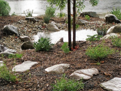
Stone or gravel can serve as a low maintenance decorative feature, but it may also serve many practical functions on the surface of an LID practice.
Stone for erosion control[edit]
Aggregates used to line swales or otherwise dissipate energy (e.g. in forebays) should have high angularity to increase the permissible shear stress applied by the flow of water. [5] However, in some surface landscaped applications there may be a desire to use a rounded aggregate such as 'river rock' for aesthetic reasons. Rounded stones should be of sufficient size to resist being moved by the flow of water. Typical stone for this purpose ranges between 50 mm and 250 mm in diameter. The larger the stone, the more energy dissipation.
- Stone beds should be twice as thick as the largest stone's diameter.
- If the stone bed is underlain by a drainage geotextile, annual inspection and possible replacement should be performed as there is a potential for clogging of this layer to occur.
Stone lining the ponding zone of this rain garden. Image credit California Native Plant Society

Coarse angular stone laid onto a geogrid and geotextile. Image from wikimedia commons


Stone mulch[edit]
Finer inorganic mulch materials can be of value applied in areas with extended ponding times i.e. in the the centre of recessed, bowl shaped bioretention, stormwater planters, trenches or swale practices. Inorganic mulches resist movement from flowing water and do not float. Applying a thin layer of inorganic mulch over the top of wood based mulch has been shown to reduce migration of the underlying layer by around 25% [6]. Inorganic mulches which may be available locally, include:
- Pea gravel
- River rock/beach stone
- Recycled glass
- Crushed mussel shells
- ↑ Ontario Ministry of Transportation, & Ontario Ministry for Transportation. (2016). Stormwater Management Requirements for Land Development Proposals. Retrieved February 26, 2018, from http://www.mto.gov.on.ca/english/publications/drainage/stormwater/section8.shtml#controls
- ↑ Drainage and Hydrology Section Transportation Engienering Branch Quality and Standards Division. (1997). MTO Drainage Management Manual. Retrieved from http://www.ontla.on.ca/library/repository/mon/12000/198363.pdf
- ↑ 3.0 3.1 Oregon State Univ., Corvallis. Dept. of Civil, Construction and Environmental Engineering.; Environmental Protection Agency, Cincinnati ONRMRL. Storm Water Management Model Reference Manual Volume I Hydrology (Revised). 2016:233.https://nepis.epa.gov/Exe/ZyPURL.cgi?Dockey=P100NYRA.txt Accessed August 23, 2017.
- ↑ Ontario Provincial Standard Specification. (2014). Construction Specification and for Seed and Cover OPSS.PROV 804. Retrieved from http://www.raqsb.mto.gov.on.ca/techpubs/ops.nsf/0/3a785d2f480f9349852580820062910a/$FILE/OPSS.PROV 804 Nov2014.pdf
- ↑ Roger T. Kilgore and George K. Cotton, (2005) Design of Roadside Channels with Flexible Linings Hydraulic Engineering Circular Number 15, Third Edition https://www.fhwa.dot.gov/engineering/hydraulics/pubs/05114/05114.pdf
- ↑ Simcock, R and Dando, J. 2013. Mulch specification for stormwater bioretention devices. Prepared by Landcare Research New Zealand Ltd for Auckland Council. Auckland Council technical report, TR2013/056