Difference between revisions of "Curb cuts"
Dean Young (talk | contribs) |
|||
| (30 intermediate revisions by 4 users not shown) | |||
| Line 1: | Line 1: | ||
| + | {{TOClimit|2}} | ||
| + | |||
| + | ==Overview== | ||
<poem> | <poem> | ||
| − | Curb cuts are a form of BMP [[Inlets|inlet]]. | + | Curb cuts are a form of LID/BMP [[Inlets|inlet]]. They include a variety of modified curbs and spillways. |
| − | They are well suited to retrofit scenarios and to collect runoff from catchments with relatively gentle longitudinal slope, and/or a greater cross slope. This might be the local topography of a parking lot or a piece of parkland | + | They are well suited to retrofit scenarios and to collect runoff from catchments with relatively gentle longitudinal slope, and/or a greater cross slope. This might be the local topography of a parking lot or a piece of parkland. |
| + | |||
As this inlet width is directly proportional to longitudinal slope; the required curb cut width increases rapidly on steeper roads. | As this inlet width is directly proportional to longitudinal slope; the required curb cut width increases rapidly on steeper roads. | ||
| − | '''Standard width (450 mm), as included in | + | '''Standard width (450 mm), as included in Ontario Provincial Standard Drawings (OPSDs) should be compared to and modified for the flow requirements of the practice.''' |
</poem> | </poem> | ||
{| class="wikitable" | {| class="wikitable" | ||
| − | |+The OPSD collection | + | |+The Ontario Provincial Standard Drawing (OPSD) collection for curb cuts |
|- | |- | ||
!Flow direction | !Flow direction | ||
| − | !From asphalt | + | !From asphalt curb and gutter |
| − | !From concrete | + | !From concrete curb and gutter |
| + | !From either asphalt or concrete outlet | ||
|- | |- | ||
| − | |30 | + | |30 to 45 degree |
|605.020 <ref name =OPSD>http://www.roadauthority.com/Standards/?id=b00e3771-6095-4257-b029-1d9879418039</ref> | |605.020 <ref name =OPSD>http://www.roadauthority.com/Standards/?id=b00e3771-6095-4257-b029-1d9879418039</ref> | ||
|605.010 <ref name =OPSD/> | |605.010 <ref name =OPSD/> | ||
| + | |605.040 Asphalt Spillways <ref name =OPSD/> | ||
|- | |- | ||
| − | |90 | + | |90 degree |
|604.020 <ref name =OPSD/> | |604.020 <ref name =OPSD/> | ||
|604.010 <ref name =OPSD/> | |604.010 <ref name =OPSD/> | ||
| + | |605.040 Asphalt Spillways <ref name =OPSD/> | ||
|} | |} | ||
==Sizing== | ==Sizing== | ||
| − | + | To completely capture linear flow travelling along a gutter perpendicular to a curb inlet, the inlet must be of width<ref>U.S. Department of Transportation, Federal Highways Administration. 2013. “URBAN DRAINAGE DESIGN MANUAL.” https://www.fhwa.dot.gov/engineering/hydraulics/pubs/10009/10009.pdf.[[File:USFHWA 2009.pdf|view here]]</ref>: | |
| − | |||
| − | |||
| − | To completely capture linear flow travelling along a gutter perpendicular to a curb inlet, the inlet must be of width:: | ||
<math>W_T=0.817Q^{0.42}S_{0}^{0.3}\left (\frac{1}{nS_{x}}\right)^{0.6}</math> | <math>W_T=0.817Q^{0.42}S_{0}^{0.3}\left (\frac{1}{nS_{x}}\right)^{0.6}</math> | ||
{{Plainlist|1=Where: | {{Plainlist|1=Where: | ||
| − | *''W<sub>T</sub>'' is the width of | + | *''W<sub>T</sub>'' is the total width of inlet for complete capture (m), |
*''Q'' is the design flow perpendicular to the inlet (m<sup>3</sup>/s) | *''Q'' is the design flow perpendicular to the inlet (m<sup>3</sup>/s) | ||
*''S<sub>0</sub>'' is the longitudinal slope ratio | *''S<sub>0</sub>'' is the longitudinal slope ratio | ||
| Line 36: | Line 40: | ||
*''S<sub>x</sub>'' is the cross slope ratio (typically between 0.015 and 0.04)}} | *''S<sub>x</sub>'' is the cross slope ratio (typically between 0.015 and 0.04)}} | ||
| − | Where the intention is to capture only a | + | The value obtained for total inlet width (''W<sub>T</sub>'') can then be divided by the chosen number of inlets to determine the required width of each individual curb cut inlet. Curb cut inlets draining roadways should be a minimum of 0.45 m in width and are typically no wider than 1.5 m. The chosen number of inlets may be adjusted up or down to ensure individual inlet widths are within this range. |
| + | |||
| + | Where the available space for curb cuts is constrained and a greater flow into the BMP is desired, the effective cross slope (''S<sub>x</sub>'') may be increased by adding a depressed concrete apron. | ||
| + | |||
| + | Where the intention is to capture only a portion of flow from the design storm event, the proportion of flow entering the curb inlet under such conditions may be calculated: | ||
<math>R_c=1-\left ( 1-\frac{W}{W_T} \right )^{1.8}</math> | <math>R_c=1-\left ( 1-\frac{W}{W_T} \right )^{1.8}</math> | ||
| Line 42: | Line 50: | ||
*''R<sub>c</sub>'' is the proportion of flow entering the curb cut, and | *''R<sub>c</sub>'' is the proportion of flow entering the curb cut, and | ||
*''W'' is the available curb cut width (m)}} | *''W'' is the available curb cut width (m)}} | ||
| − | |||
| − | |||
==Example== | ==Example== | ||
| − | + | Three (3) curb cut inlets of 1 m width each, representing a total curb cut width of 3 m, are proposed for an offline [[Bioretention|bioretention cell]] receiving runoff from an adjacent roadway. The gutter and the curb are made from smooth concrete with Manning's 'n' = 0.013. The cross slope ratio is 3% and the longitudinal slope of the road is 2%. The 1 in 25 year design storm produces a peak flow of 0.08 m<sup>3</sup>/s from the road drainage area. | |
| − | The width of | + | The total width of curb cut inlets required to capture 100% of this flow is: |
<math>W_T=0.817\times(0.08)^{0.42}\times(0.02)^{0.3}\left (\frac{1}{0.013\times0.03}\right)^{0.6}=9.71\ m</math> | <math>W_T=0.817\times(0.08)^{0.42}\times(0.02)^{0.3}\left (\frac{1}{0.013\times0.03}\right)^{0.6}=9.71\ m</math> | ||
| − | The proportion of water entering the bioretention cell under | + | The proportion of water entering the bioretention cell under peak flow conditions during the design storm event would be: |
<math>R_c=1-\left ( 1-\frac{3}{9.71} \right )^{1.8}= 0.48</math> | <math>R_c=1-\left ( 1-\frac{3}{9.71} \right )^{1.8}= 0.48</math> | ||
| − | 48% of the 0.08 m<sup>3</sup>/s (i.e. 0.038 m<sup>3</sup>/s) would enter the bioretention cell through the | + | So only 48% of the 0.08 m<sup>3</sup>/s (i.e. 0.038 m<sup>3</sup>/s) would enter the bioretention cell through the inlets as designed. |
==Curb cuts gallery== | ==Curb cuts gallery== | ||
{{:Curb cuts: Gallery}} | {{:Curb cuts: Gallery}} | ||
---- | ---- | ||
| − | [[category: | + | [[category: Calculations]] |
| + | |||
| + | ==References== | ||
Latest revision as of 21:45, 23 October 2023
Overview[edit]
Curb cuts are a form of LID/BMP inlet. They include a variety of modified curbs and spillways.
They are well suited to retrofit scenarios and to collect runoff from catchments with relatively gentle longitudinal slope, and/or a greater cross slope. This might be the local topography of a parking lot or a piece of parkland.
As this inlet width is directly proportional to longitudinal slope; the required curb cut width increases rapidly on steeper roads.
Standard width (450 mm), as included in Ontario Provincial Standard Drawings (OPSDs) should be compared to and modified for the flow requirements of the practice.
| Flow direction | From asphalt curb and gutter | From concrete curb and gutter | From either asphalt or concrete outlet |
|---|---|---|---|
| 30 to 45 degree | 605.020 [1] | 605.010 [1] | 605.040 Asphalt Spillways [1] |
| 90 degree | 604.020 [1] | 604.010 [1] | 605.040 Asphalt Spillways [1] |
Sizing[edit]
To completely capture linear flow travelling along a gutter perpendicular to a curb inlet, the inlet must be of width[2]:

Where:
- WT is the total width of inlet for complete capture (m),
- Q is the design flow perpendicular to the inlet (m3/s)
- S0 is the longitudinal slope ratio
- n is Manning's 'n' (between 0.012 and 0.016 for concrete, depending on surface treatment), and
- Sx is the cross slope ratio (typically between 0.015 and 0.04)
The value obtained for total inlet width (WT) can then be divided by the chosen number of inlets to determine the required width of each individual curb cut inlet. Curb cut inlets draining roadways should be a minimum of 0.45 m in width and are typically no wider than 1.5 m. The chosen number of inlets may be adjusted up or down to ensure individual inlet widths are within this range.
Where the available space for curb cuts is constrained and a greater flow into the BMP is desired, the effective cross slope (Sx) may be increased by adding a depressed concrete apron.
Where the intention is to capture only a portion of flow from the design storm event, the proportion of flow entering the curb inlet under such conditions may be calculated:

Where:
- Rc is the proportion of flow entering the curb cut, and
- W is the available curb cut width (m)
Example[edit]
Three (3) curb cut inlets of 1 m width each, representing a total curb cut width of 3 m, are proposed for an offline bioretention cell receiving runoff from an adjacent roadway. The gutter and the curb are made from smooth concrete with Manning's 'n' = 0.013. The cross slope ratio is 3% and the longitudinal slope of the road is 2%. The 1 in 25 year design storm produces a peak flow of 0.08 m3/s from the road drainage area.
The total width of curb cut inlets required to capture 100% of this flow is:

The proportion of water entering the bioretention cell under peak flow conditions during the design storm event would be:

So only 48% of the 0.08 m3/s (i.e. 0.038 m3/s) would enter the bioretention cell through the inlets as designed.
Curb cuts gallery[edit]
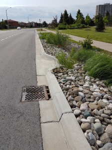
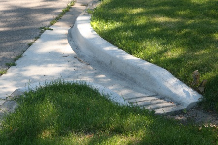
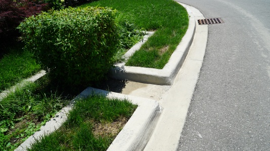
OPSD 605.040 Asphalt Spillway inlet to biofilter swale and road catch basin overflow outlet. County Court Blvd., Brampton, ON.
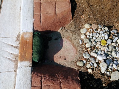
This curb cut has been sawn into existing concrete as part of a retrofit. Note the temporary (erosion log) and permanent stone erosion control measures in place. Mississauga Road, ON.
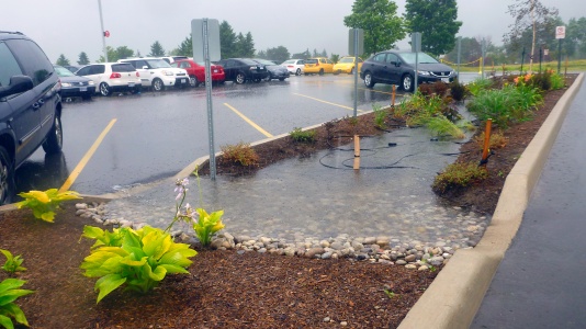
Curb cut used as a controlled overflow route from permeable pavements to a bioretention facility with monitoring well, Lake Simcoe Region Conservation Authority, Newmarket, ON.
Curb cut into a bioretention facility in Brown Deer, WI. Stone is used to reduce erosion around the inlet area. Photo credit: Aaron Volkening
Curb cut into a bioretention facility in Ajax, ON.
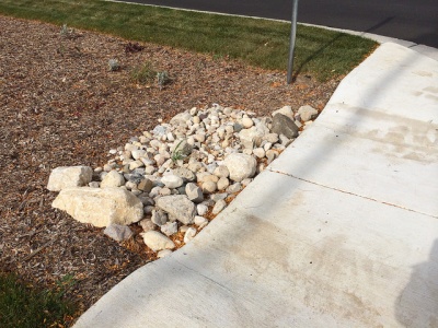
Stone lined inlet at IMAX site in Mississauga
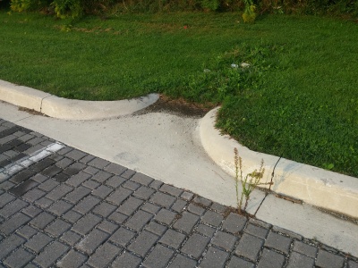
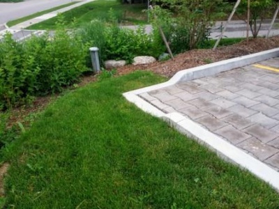
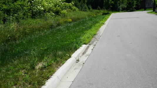
The grading around this inlet prevents flow in the correct direction. i.e. from the pavement onto the grass. Not too critical in this example, as the surface is permeable pavements.
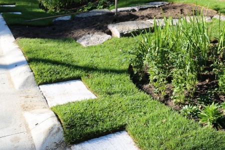
Curb cut into a rain garden on a green street in Newmarket, ON.
Curb cut leading into a small bioretention cell in Brampton, ON.
Curb cut leading to a bioswale in Brampton, ON.


References[edit]
- ↑ 1.0 1.1 1.2 1.3 1.4 1.5 http://www.roadauthority.com/Standards/?id=b00e3771-6095-4257-b029-1d9879418039
- ↑ U.S. Department of Transportation, Federal Highways Administration. 2013. “URBAN DRAINAGE DESIGN MANUAL.” https://www.fhwa.dot.gov/engineering/hydraulics/pubs/10009/10009.pdf.File:USFHWA 2009.pdf