Difference between revisions of "Curb cuts"
Jenny Hill (talk | contribs) |
Jenny Hill (talk | contribs) |
||
| Line 5: | Line 5: | ||
{{Plainlist|1=Where: | {{Plainlist|1=Where: | ||
*''W<sub>T</sub>'' is the width of the inlet in m, | *''W<sub>T</sub>'' is the width of the inlet in m, | ||
| − | *''Q'' is the flow perpendicular to the inlet in m<sup>3</sup | + | *''Q'' is the flow perpendicular to the inlet in m<sup>3</sup>/s |
*''S<sub>0</sub>'' is the longitudinal slope | *''S<sub>0</sub>'' is the longitudinal slope | ||
*''n'' is Manning's 'n' (between 0.012 and 0.016 for concrete, depending on surface treatment), | *''n'' is Manning's 'n' (between 0.012 and 0.016 for concrete, depending on surface treatment), | ||
Revision as of 20:21, 29 September 2017
Sizing[edit]
To completely capture linear flow travelling along a gutter perpendicular to a curb inlet, the inlet must be of width::

Where:
- WT is the width of the inlet in m,
- Q is the flow perpendicular to the inlet in m3/s
- S0 is the longitudinal slope
- n is Manning's 'n' (between 0.012 and 0.016 for concrete, depending on surface treatment),
- Sx is the cross slope
Where the intention is to capture only a proportion of the flow, the ratio of flow entering the curb inlet may be calculated::

Example[edit]
A curb cut of 3 m is proposed as an inlet for an offline bioretention cell receiving runoff from an adjacent roadway. The gutter and the curb are made from smooth concrete with Manning's 'n' = 0.013. The x-slope is 3% and the longitudinal slope of the road is 2%. The design storm produces flow of 0.08 m3/s.
The width of inlet to capture 100% of this flow is::

The proportion of water entering the bioretention cell under these flow conditions would be::

48% of the 0.08 m3/s flow would enter the bioretenteion cell through the inlet as designed.
Curb cuts Gallery[edit]
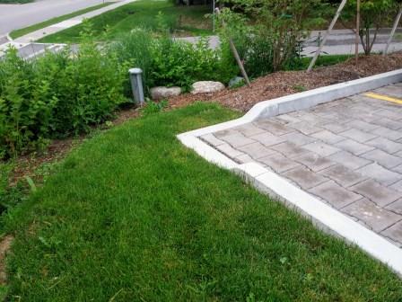
Curb cut used as a controlled overflow route from permeable paving to a bioretention facility with monitoring well, Lake Simcoe Region Conservation Authority, Newmarket, ON
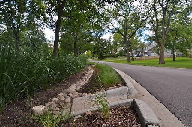
Curb cut into a bioretention facility in Hinsdale, IL.
Decorative aggregate in the center of the facility reduces erosion and dissipates power inflow around the inlet area. A monitoring/maintenance well can be seen in the foreground.
Photo credit: CNT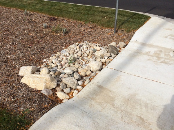
Curb cut into a bioretention facility in Brown Deer, WI.
Aggregate is used to reduce erosion around the inlet area.
Photo credit: Aaron Volkening


