Difference between revisions of "Check dams"
Jenny Hill (talk | contribs) m |
Jenny Hill (talk | contribs) |
||
| Line 8: | Line 8: | ||
*should have energy dissipation and erosion control measures installed in the 1 - 2 m downstream. Examples include large aggregate or [[Turf reinforcement|turf reinforcement]]}} | *should have energy dissipation and erosion control measures installed in the 1 - 2 m downstream. Examples include large aggregate or [[Turf reinforcement|turf reinforcement]]}} | ||
| − | + | ==Sizing and spacing of check dams== | |
| − | '''[[ | + | [[File:Check dams.png|thumb]] |
| + | Check dams are a feature of [[enhanced grass swales]]. They promote [[infiltration]] and evaporation by promoting limited ponding. | ||
| + | To design [[check dams]] into a swale: | ||
| + | #The height of each dam is determined by the depth of ponded water that will infiltrate in a specified period (often 48 - 72 hours). The infiltration may be through the [[turf]] grass or other [[plants]] directly into the native soil or some [[soil amendments]] may be proposed in the design. | ||
| + | #The gradient between the top of the lower check dam and the bottom of the upper one is called "compensation gradient" which is the future or final effective gradient of the swale. It is formed when material carried by flowing water fills the check dams to spillway level. | ||
| + | #Dams are usually installed between 10-20 m along the swale. The spaces between check dams can be determined according to the compensation gradient and the effective height of the dams. They are distributed such that the crest of each dam is at approximately the same elevation as the toe of the upstream dam. If the slope along the swale varies, so should the distance between the dams. | ||
| + | #The compensation gradient of enhanced swales must be < 1 % (0.5% preferred). | ||
| + | |||
| + | The objective of these design recommendations are to maximize the distribution of ponded water along the whole BMP. Detailed design may require iteration of the dam heights and distances along each section of a long swale. | ||
| + | ---- | ||
| + | <div style="float: right">{{#widget:WolframAlpha|id=a04d99bf6eaf9309e13e0b359f7368e2}}{{#widget:WolframAlpha|id=edc4fd3f7f54774d9ab0471f34d6041c}}</div> | ||
| + | To estimate the depth of water that can be infiltrated into a surface within a given time:: | ||
| + | <math>y=f\times t</math> | ||
| + | |||
| + | {{Plainlist|1=Where: | ||
| + | *''y'' = the depth of ponded water in mm, | ||
| + | *''f''' = the [[design infiltration rate]] in mm/hr (after correction, where required). | ||
| + | *''t'' = time in hrs}} | ||
| + | ---- | ||
| + | After surveying the longitudinal profile of the swale, the number of check dams for the swale can be calculated by using the following equation: | ||
| + | |||
| + | :<math>Number\ of\ dams= \frac{L\left ( S_{i}-S_{e} \right )}{h}</math> | ||
| + | |||
| + | {{Plainlist|1= Where: | ||
| + | *''L'': Length of swale (m) | ||
| + | *''S<sub>i</sub>'': Initial existing slope ratio of the swale (rise/run) | ||
| + | *''S<sub>e</sub>'': Desired effective slope of the enhanced swale (between 0.005 - 0.01, rise/run) | ||
| + | *''h'': The average effective height of the check dams in m (excluding foundations)}} | ||
| + | ---- | ||
| + | *The first check dam should be constructed on a stable point in the gully such as a rock outcrop, the junction point of the gully to a road, the main stream or river, lake or reservoir. | ||
| + | *If there is no such stable point, a counter-dam must be constructed. The distance between the first dam and the counter-dam must be at least two times the effective height of the first check dam. | ||
| + | *The points where the ensuing check dams are to be built are determined according to the compensation gradient and the effective height of the check dams. | ||
| + | *The effective height of the second check dam is determined by taking into account the depth of the swale, the depth of the spillway and the maximum height of the check dam. | ||
| + | *In this way, all the other proposed check dam points can be calculated. | ||
| + | |||
| + | When spacing check dams, give preference to the narrowest parts of the swale in order to reduce construction costs. | ||
| + | In this case, to establish the compensation gradient between the proposed check dams, proportionately increase the foundation depth of the upper check dam when the space between the lower and upper check dam is extended. | ||
| + | When the space is shortened, decrease the foundation depth. | ||
| + | As the foundation depth is increased, the total height of the check dam (effective height plus foundation depth) should not exceed the permissible, maximum total height. | ||
| + | |||
| + | ==Example Calculation== | ||
| + | An enhanced swale of 42 m has an existing longitudinal slope of 6 %. The underlying soil has been amended to infiltrate at 16 mm/hr (after safety correction applied); the regulatory authority requires that ponded water must not remain for over 48 hours. | ||
| + | The maximum height of the check dams (h) to prevent extended ponding is:: | ||
| + | <math>h=16\ mm/hr\times 48\ hrs = 768\ mm </math> | ||
| + | |||
| + | But the maximum recommended depth of check dams is 0.6 m (600 mm). | ||
| + | |||
| + | (As an aside, these will drain in <math>\frac{600\ mm}{16\ mm/hr}=37.5\ hrs</math>) | ||
| + | |||
| + | The current vertical distance along the swale is:: | ||
| + | <math>42\ m\times \left ( \frac{6}{100} \right )=2.52\ m</math> | ||
| + | |||
| + | The desired effective slope to slow flow is 0.5%. The vertical distance along the swale with compensation gradient is:: | ||
| + | <math>42\ m\times \left ( \frac{0.5}{100} \right )=0.21\ m</math> | ||
| + | |||
| + | The number of check dams required is:: | ||
| + | <math>\frac{\left ( 2.52\ m\times 0.21\ m\right )}{0.6\ m}=3.85</math> | ||
| + | |||
| + | This is rounded up to 4 dams, creating 5 ponding zones:: | ||
| + | |||
| + | <math>\frac{42\ m}{5}=8.4\ m</math> | ||
| + | |||
| + | So the four check dams will be 0.6 m high and spaced every 8.4 m along the swale. These are fairly close together, but this construction is achievable and the dimensions are not remarkable, given the change in gradient is an order of magnitude. | ||
| + | |||
| + | ==External references== | ||
| + | [http://www.fao.org/docrep/006/ad082e/AD082e02.htm FAO] | ||
| + | |||
| + | [[Category:Modeling]] | ||
==Gallery== | ==Gallery== | ||
{{:Check dams: Gallery}} | {{:Check dams: Gallery}} | ||
Revision as of 13:34, 28 March 2018
Check dams are small dams or weirs constructed across a drainage ditch, swale, or channel to lower the speed of concentrated flows for a certain design range of storm events and to promote infiltration.
Check dams:
- may be constructed of any resilient and waterproof material, including: rock gabions, earth berms, coarse aggregate or rip-rap, concrete, metal or pre-treated timber. Rocks used in check dams should have median diameter 25 - 75 mm.
- for enhanced swales may be up to 0.6 m in height; the maximum design depth of ponded water should be ≤ 0.6 m.
- designed for higher flow velocities should have spillways incorporated into their profile, to direct water to the centre of the swale.
- are usually installed between 10-20 m along the swale. The spacing of dams should not exceed the horizontal distance from the toe of the upstream dam to the same elevation on the downstream dam.
- should have energy dissipation and erosion control measures installed in the 1 - 2 m downstream. Examples include large aggregate or turf reinforcement
Sizing and spacing of check dams[edit]

Check dams are a feature of enhanced grass swales. They promote infiltration and evaporation by promoting limited ponding. To design check dams into a swale:
- The height of each dam is determined by the depth of ponded water that will infiltrate in a specified period (often 48 - 72 hours). The infiltration may be through the turf grass or other plants directly into the native soil or some soil amendments may be proposed in the design.
- The gradient between the top of the lower check dam and the bottom of the upper one is called "compensation gradient" which is the future or final effective gradient of the swale. It is formed when material carried by flowing water fills the check dams to spillway level.
- Dams are usually installed between 10-20 m along the swale. The spaces between check dams can be determined according to the compensation gradient and the effective height of the dams. They are distributed such that the crest of each dam is at approximately the same elevation as the toe of the upstream dam. If the slope along the swale varies, so should the distance between the dams.
- The compensation gradient of enhanced swales must be < 1 % (0.5% preferred).
The objective of these design recommendations are to maximize the distribution of ponded water along the whole BMP. Detailed design may require iteration of the dam heights and distances along each section of a long swale.
To estimate the depth of water that can be infiltrated into a surface within a given time::

Where:
- y = the depth of ponded water in mm,
- f' = the design infiltration rate in mm/hr (after correction, where required).
- t = time in hrs
After surveying the longitudinal profile of the swale, the number of check dams for the swale can be calculated by using the following equation:

Where:
- L: Length of swale (m)
- Si: Initial existing slope ratio of the swale (rise/run)
- Se: Desired effective slope of the enhanced swale (between 0.005 - 0.01, rise/run)
- h: The average effective height of the check dams in m (excluding foundations)
- The first check dam should be constructed on a stable point in the gully such as a rock outcrop, the junction point of the gully to a road, the main stream or river, lake or reservoir.
- If there is no such stable point, a counter-dam must be constructed. The distance between the first dam and the counter-dam must be at least two times the effective height of the first check dam.
- The points where the ensuing check dams are to be built are determined according to the compensation gradient and the effective height of the check dams.
- The effective height of the second check dam is determined by taking into account the depth of the swale, the depth of the spillway and the maximum height of the check dam.
- In this way, all the other proposed check dam points can be calculated.
When spacing check dams, give preference to the narrowest parts of the swale in order to reduce construction costs. In this case, to establish the compensation gradient between the proposed check dams, proportionately increase the foundation depth of the upper check dam when the space between the lower and upper check dam is extended. When the space is shortened, decrease the foundation depth. As the foundation depth is increased, the total height of the check dam (effective height plus foundation depth) should not exceed the permissible, maximum total height.
Example Calculation[edit]
An enhanced swale of 42 m has an existing longitudinal slope of 6 %. The underlying soil has been amended to infiltrate at 16 mm/hr (after safety correction applied); the regulatory authority requires that ponded water must not remain for over 48 hours. The maximum height of the check dams (h) to prevent extended ponding is::

But the maximum recommended depth of check dams is 0.6 m (600 mm).
(As an aside, these will drain in )

The current vertical distance along the swale is::

The desired effective slope to slow flow is 0.5%. The vertical distance along the swale with compensation gradient is::

The number of check dams required is::

This is rounded up to 4 dams, creating 5 ponding zones::

So the four check dams will be 0.6 m high and spaced every 8.4 m along the swale. These are fairly close together, but this construction is achievable and the dimensions are not remarkable, given the change in gradient is an order of magnitude.
External references[edit]
Gallery[edit]
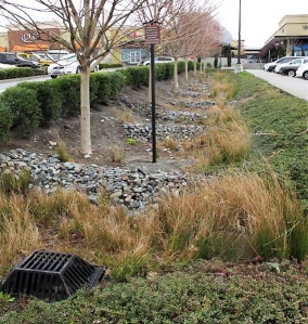
Enhanced swale with rocky check dams and a metal overflow grate in Northgate Mall parking lot, Seattle. Photo credit: MLSmith
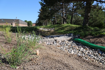
Bioswale with rock check dams to slow down the water, encouraging infiltration. Note the biodegradable erosion control blanket still in place. LSRCA headquarters, 2017
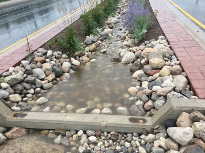
A check dam in action, effectively pooling water.
A swale during a rain event, with concrete check dams, armourstone, mulch and Tall grasses to slow down moving water (as shown in the .gif file) to promote infiltration in the feature.


Also see Jen's Pinterest board of check dams