Difference between revisions of "Bioswales"
| Line 1: | Line 1: | ||
| − | + | <imagemap> | |
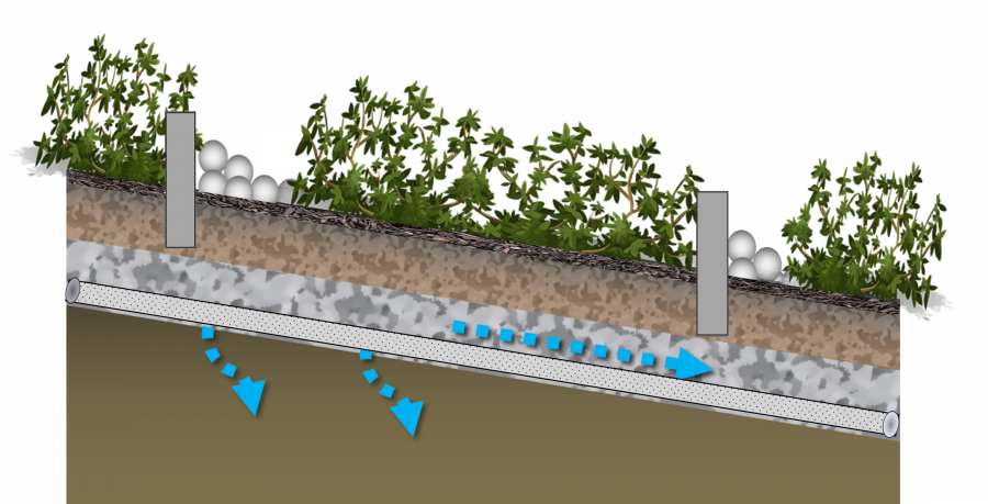
| + | File:Unlabelled bioswale underdrain.png|thumb|900px|Bioswale with check dams, to facilitate short-term ponding (vertical scale exaggerated for diagram), graded sloped channel, mulch preserve soil moisture for plant survival to maintain the organic matter content of underlying filter media, filter media and vegetation to promote infiltration into the facility, an underdrain and river rock/stone to reduce flow velocity and erosion potential within the facility. <span style="color:red">''A note: The following is an "image map", feel free to explore the image with your cursor and click on highlighted labels that appear to take you to corresponding pages on the Wiki.''</span> | ||
| − | + | rect 160 131 656 720 [[Graminoids: List|Tall Grasses / Vegetation]] | |
| + | poly 11177 262 1170 820 2741 1069 2768 565 [[Graminoids: List|Tall Grasses / Vegetation]] | ||
| + | rect 3106 580 3729 1207 [[Graminoids: List|Tall Grasses / Vegetation]] | ||
| + | poly 787 510 784 765 1156 814 1156 693 [[Stone|River Rock]] | ||
| + | rect 2875 903 3102 1113 [[Stone|River Rock]] | ||
| + | poly 773 745 777 814 2744 1117 2741 1069 [[Mulch|Mulch]] | ||
| + | poly 2878 1141 2882 1086 3540 1193 3547 1258 [[Mulch|Mulch]] | ||
| + | rect 656 438 773 982 [[Check dams|Check Dams]] | ||
| + | rect 2872 1317 2751 755 [[Check dams|Check Dams]] | ||
| + | poly 777 814 773 1013 2741 1327 2737 1113 [[Bioretention: Filter media|Filter Media]] | ||
| + | poly 270 720 267 941 653 996 653 800 [[Bioretention: Filter media|Filter Media]] | ||
| + | poly 2872 1134 2868 1341 3547 1465 3537 1262 [[Bioretention: Filter media|Filter Media]] | ||
| + | poly 267 941 264 1100 3537 1630 3543 1465 [[Reservoir aggregate|Reservoir Aggregate]] | ||
| + | poly 270 1103 260 1182 3530 1720 3537 1630 [[Underdrains|Underdrain]] | ||
| + | poly 264 1203 267 1979 3543 1982 3540 1744 [[Soil groups|Native Soil]] | ||
| − | + | </imagemap> | |
| − | + | {{TOClimit|2}} | |
| − | |||
| − | |||
| − | |||
| − | |||
| − | |||
| − | |||
| − | |||
| − | |||
| − | |||
| − | |||
| − | |||
| − | |||
| − | |||
| − | |||
| − | |||
| − | |||
| − | |||
| − | |||
| − | |||
| − | |||
| − | |||
| − | |||
| − | |||
| − | |||
| Line 43: | Line 34: | ||
| + | *This article is about installations designed to capture and convey surface runoff along a vegetated channel, whilst also promoting infiltration. | ||
| + | *For underground conveyance which promotes infiltration, see [[Exfiltration trenches]]. | ||
| + | *For design recommendations on channels in which surface flow is controlled with [[check dams]], see [[Enhanced swales]]. | ||
==Overview== | ==Overview== | ||
Revision as of 21:08, 14 January 2022
- This article is about installations designed to capture and convey surface runoff along a vegetated channel, whilst also promoting infiltration.
- For underground conveyance which promotes infiltration, see Exfiltration trenches.
- For design recommendations on channels in which surface flow is controlled with check dams, see Enhanced swales.
Overview[edit]
The fundamental components of a bioswale are:
- A graded channel
- Planting
- Underdrain with clean out and inspection ports
- Filter media, to permit infiltration into the facility (not necessarily to soils below)
Additional components may include:
- Impermeable liner to prevent infiltration to soils below
- Check dams to facilitate short tern ponding
Planning considerations[edit]
Bioswales are sized as narrow linear bioretention cells. Drainage time of bioswales is typically lower than other geometric configurations of similarly sized bioretention facilities, owing to the higher hydraulic radius of the sides.
Design[edit]
Inlets[edit]
Overview[edit]
Concentrated flow inlets are associated with LID practices such as Bioretention, Stormwater planters, Infiltration trenches and chambers. Sheet flow alternatives include level spreaders, gravel diaphragms and vegetated filter strips. Practices such as permeable pavements and green roofs receive precipitation directly, whilst exfiltration trenches are connected directly to conventional storm sewers.
Inlets for BMPs in the right of way should be located:
- At all sag points in the gutter grade
- Immediately upgrade of median breaks, crosswalks, and street intersections.
It is recommended to include multiple inlets, sized to distribute inflow along the length of the practice or between multiple facilities, where feasible, rather than concentrating all inflow into a single location. (Offline overflow).
Trench drains[edit]
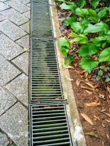
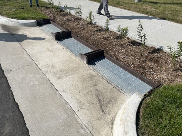
Trench drains are long, covered channels that collect and direct water into the BMP. They are an excellent solution for streets where walking across the entire surface is to be encouraged. They can be designed as detectable edges or part of a detectable edge, and may be used to help define curbless or 'complete streets'.
Trenches may either be shallow (where runoff volume is less of an issue) or deep and covered by a metal grate. Deeper trench drains may gather sediment and require frequent maintenance.
Drains may be configured either perpendicular or parallel to the flow direction of the roadway, collecting runoff and directing to a single inlet in the BMP.
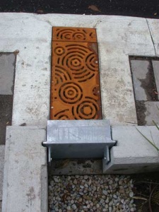
Combination of trench drain and winter shut off gate: King Street, Kitchener, ON
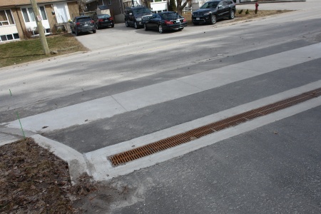
Trench drain that outlets to a bioswale at the LSRCA Office in Newmarket, ON
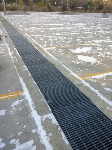
Trench drain in parking lot of Evergreen brickworks, Toronto ON

Bioretention system, or rain garden with a decorative trench drain cover, in Portland, US Taken in April 2013. Photo credit:EmilyBlueGreen
This trench drain has easily opened, hinged sections for maintenance, Singpore


Curb cuts[edit]
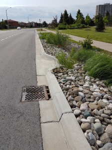
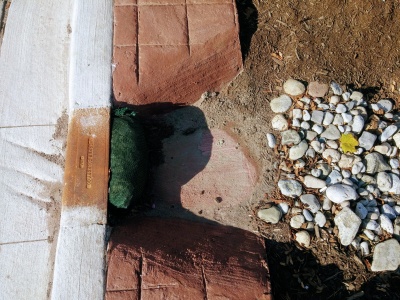
Curb cuts are breaks along the length of a curb system to allow water to flow into a LID/BMP.
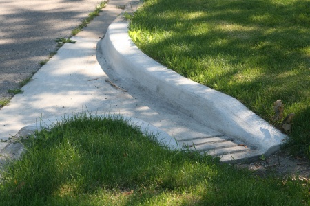
Inlet aprons or depressions increase inflow effectiveness of curb cuts. Steeply angled aprons can be hazardous, especially to people bicycling. Curbside and protected bike lanes along concrete aprons should be at least 1.8 m to give cyclists adequate clear width from the curb and any pavement seams. Aprons can also be marked visually to indicate their perimeter. For aprons into bioretention, the curb may angle into the cell to improve conveyance of gutter flow into the facility. Aprons typically drop 50 mm into the bioretention cell, with another 50 mm drop behind the curb to maintain inflow as debris collects. A depressed concrete apron can be cast in place or retrofitted in by grinding down the existing concrete pavement.
Where the curb alignment along the street is straight, the curb opening may optionally have a bar across the top of the inlet.
See Curb cuts for further details and references to Ontario Provincial Standard Drawings.
OPSD 605.040 Asphalt Spillway inlet to biofilter swale and road catch basin overflow outlet. County Court Blvd., Brampton, ON.
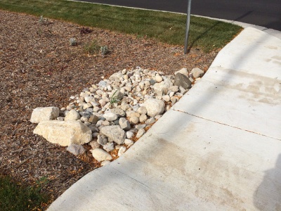
This curb cut has been sawn into existing concrete as part of a retrofit. Note the temporary (erosion log) and permanent stone erosion control measures in place. Mississauga Road, ON.
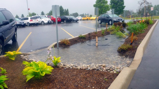
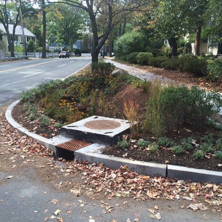
Curb cut used as a controlled overflow route from permeable pavement to a bioretention facility with monitoring well, Lake Simcoe Region Conservation Authority, Newmarket, ON.
Curb cut into a bioretention facility in Brown Deer, WI. Stone is used to reduce erosion around the inlet area. Photo credit: Aaron Volkening
Curb cut into a bioretention facility in Ajax, ON.
Stone lined inlet at IMAX site in Mississauga
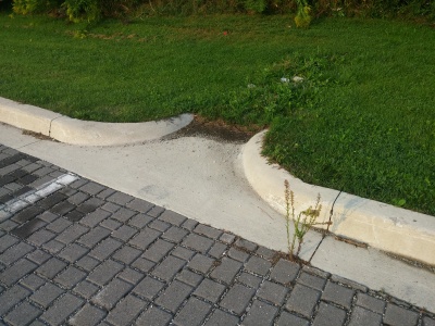
The grading around this inlet prevents flow in the correct direction. i.e. from the pavement onto the grass. Not too critical in this example, as the surface is permeable pavement.


Inlet sumps[edit]
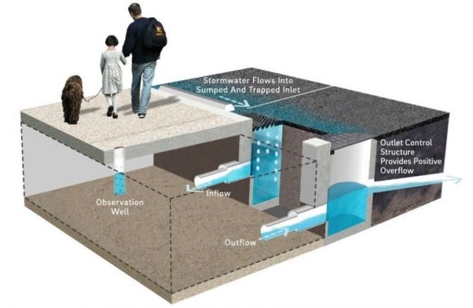
An inlet sump is recommended to settle and separate sediments from runoff where a large amount of debris is expected. Water drains into a catch basin, where debris settles in its sump. After pretreatment, water drains via a pipe or opening into the BMP. The sump can be directly connected to a perforated underdrain pipe to distribute the flow to the bioretention, supported soil cells or underground practices such as trenches or chambers.
Sump inlets should not be sited where pedestrians will have to negotiate with them.
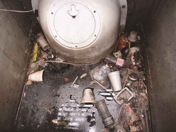
This pretreatment device, known as a baffle helps to remove trash, oil, TSS, larger sediments (silts, sands, etc.) and other floatables in roadway catch basins. This picture was taken of a SNOUT BAFL in Myrtle Beach, S.C. (Mullen, 2022)[1]
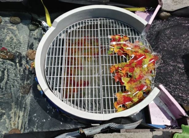
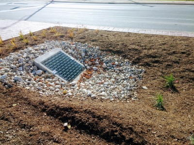
Example of an overland flow sump, capturing stormwater runoff from the adjacent roadway. This example showcases a Rain Guardian(TM) Turret structure with a metal grate overtop to capture larger floatables, trash and detritus from entering a stormwater facility or in this case a bioretention LID feature[2].
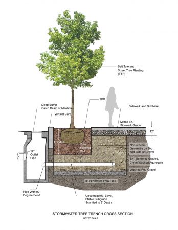
A stormwater tree trench, including a sump inlet design used as part of pretreatment. The feature is located in the City of Cambridge, Massachusetts, US. The design was developed and lead by HDR Inc., and Halvorson, Tighe & Bond Studio (Halvorson, Tighe & Bond Studio, n.d.)[3]
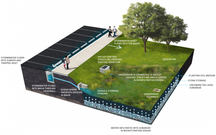
Example of a sump inlet being used in conjunction with a large bioretention basin feature, located in park space receiving stormwater off of the adjacent roadway (Source: Philadelphia Water Department, n.d.)[4]
An inlet sump leading into a bioretention bump out for traffic calming. Inlet sumps help both settle and separate sediment from stormwater road runoff before depositing excess sediment and silt into an infiltration BMP. These sumps allow stormwater to flow into the feature through an underdrain pipe (Source: NACTO, 2017)[5]
Example of a sump inlet allowing sediment to settle out of influent stormwater before entering a large infiltration chamber housed under the parking lot (Source: Philadelphia Water Department. 2020)[6]
Example of a proprietary inlet device known as a Rain Guardian Bunker, that was installed at the Morningside Extension Project in Scarborough, ON.


Depressed drains[edit]
Runoff in the gutter drops into a grate-covered drain before flowing into the BMP. Drain covers must be compatible with bicycling and walking; grid covers are preferred. Depressed drains are a potential solution for bioretention cells on sloped streets where directing runoff into the cell is a challenge.
This style of inlet can be combined with a curb cut, to maintain capacity in case debris clogs the grate. Template:Trench drains: Gallery
External links[edit]
Overflow[edit]

Routing[edit]
- Infiltration facilities can be designed to be inline or offline from the drainage system. See figure to the right for an illustration.
- Inline facilities accept all of the flow from a drainage area and convey larger event flows through an overflow outlet. The overflow must be sized to safely convey larger storm events out of the facility. The overflow must be situated at the maximum surface ponding elevation or furthest downgradient end of the facility to limit surface ponding during periods of flow in excess of the facility storage capacity.
- Offline facilities use flow splitters or bypass channels that only allow the design storm runoff storage volume to enter the facility. Higher flows are conveyed to a downstream storm sewer or other BMP by a flow splitting manhole weir or pipe, or when the maximum surface ponding depth has been reached, by by-passing the curb opening and flowing into a downstream catchbasin connected to a storm sewer.
Overflow Elevation[edit]
The invert of the overflow should be placed at the maximum water surface elevation of the practice (i.e. the maximum surface ponding level). A good starting point is 150 to 350 mm above the surface of the mulch cover. However, consideration should be given to public safety, whether or not an underdrain is included, the time required for ponded water to drain through the filter bed surface, and if no underdrain is present, into the underlying native soil (must drain within 48 hours). See Bioretention: Sizing and Stormwater planters for more details.
Freeboard[edit]
- In swales conveying flowing water a freeboard of 300 mm is generally accepted as a good starting point.
- In bioretention the freeboard is the difference between the invert elevation of the inlet and overflow structure. 150 mm will usually suffice, so long as the inlet will not become inundated during design storm conditions.
- In above grade stormwater planters, the equivalent dimension would be the difference between the invert elevation of the lip of the planter and the overflow structure (150 mm minimum).
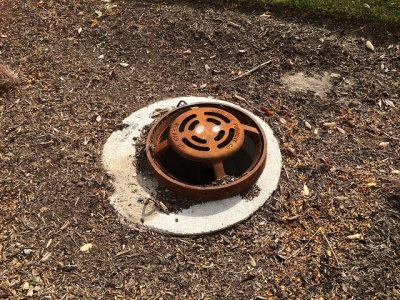
Overflow Outlet Options[edit]
Metal grates are recommended (over plastic) in all situations.
| Feature | Anti Vandalism/Robust | Lower Cost Option | Self cleaning |
|---|---|---|---|
| Dome grate | x | ||
| Flat grate | x | ||
| Catch basin | x | ||
| Ditch inlet catch basin | x | x | |
| Curb cut | x | x | x |
Gallery[edit]
Flat metal overflow with stone surround to reduce erosion around the cast concrete structure. Mississauga Road, ON
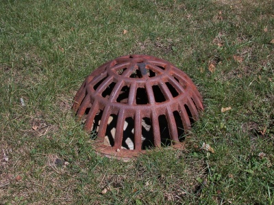
Domed, metal overflow grate. Being flush with the surface reduces potential infiltration of ponded water. Photo credit: Aaron Volkening
Overflow inlet for newly constructed stormwater bioretention areas in median of Bradley Road. Village of Brown Deer, Wisconsin. Bradley Road, east of 51st Street. Photo from October 2015. Constructed summer 2015.
Photo credit: Aaron Volkening
Flat, metal overflow grate in Emeryville California Stormwater Curb Extension
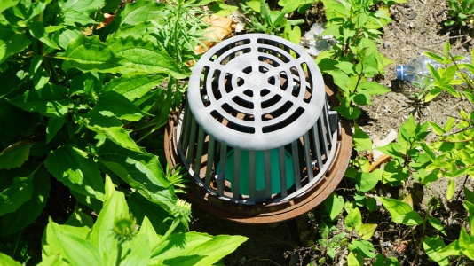
Note the greyish colour change indicating UV degradation of this plastic overflow inlet in a bioretention cell; metal is recommended instead. Mississauga ON.


Materials[edit]
All forms of bioretention are complex in their structure, so please follow separate links for the materials.
Gallery[edit]

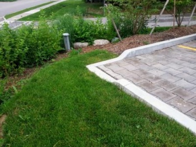
Streetside swale in Seattle
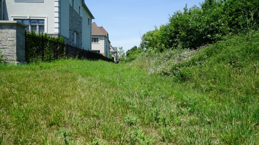
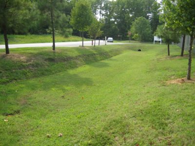
This feature is a bioswale in that the underlying soil has been replaced with engineered filter media. The turf finish simplifies landscape maintenance. Brampton, ON
A bioswale located on Country Court Blvd., located in Brampton, ON> Read more about the performance of this feature and associated rpoject, by reading the following Grey to Green Conference Presentation, 2018. Dean Young - STEP, 2018
Bioswale located in Downsview Park, Toronto ON. with Check dams.
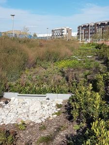
Grassed bioswale with Vegetated filter strips
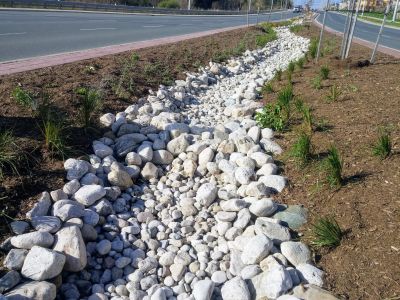
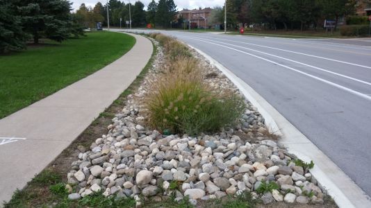
Stone-lined bioswale with rock check dams located to helps slow the flow of water as it enter the system from the nearby roads. [[ STEP, 2017

.jpg)


Planting Design Considerations[edit]
- Where possible a combination of native trees, shrubs and perennial herbs should be used in addition to grasses.
- Most bioswales will be situated to receive full sun exposure. The ‘Exposure’ column in the master plant list identifies the sun exposure condition for each species.
- Facilities with a deeper media bed (greater than 1 m) provide the opportunity for a wider range of plant species (including trees).
- For applications along roads and parking lots, where snow may be plowed or stored, non-woody and salt tolerant species should be chosen.
- Proper spacing must be provided for aboveground and below ground utilities, and adjacent infrastructure.
Performance[edit]
While few field studies of the pollutant removal capacity of bioswales are available from cold climate regions like Ontario, it can be assumed that they would perform similar to bioretention cells. Bioretention provides effective removal for many pollutants as a result of sedimentation, filtering, plant uptake, soil adsorption, and microbial processes. It is important to note that there is a relationship between the water balance and water quality functions. If a bioswale infiltrates and evaporates 100% of the flow from a site, then there is essentially no pollution leaving the site in surface runoff. Furthermore, treatment of infiltrated runoff will continue to occur as it moves through the native soils.
| LID Practice | Location | Runoff Reduction* | Reference |
|---|---|---|---|
| Bioswale without underdrain | Washington | 98% | Horner et al. (2003)[7] |
| Scotland | 94% | Jefferies (2005)[8] | |
| Bioswale with Underdrain | Maryland | 46 to 54% | Stagge (2006)[9] |
| Bioretention without underdrain | China | 85 to 100%* | Gao, et al. (2018)[10] |
| Connecticut | 99% | Dietz and Clausen (2005) [11] | |
| Pennsylvania | 80% | Ermilio (2005)[12] | |
| Pennsylvania | 70% | Emerson and Traver (2004)[13] | |
| Bioretention with underdrain | |||
| Ontario | 64% | CVC (2020)[14] | |
| Maryland and North Carolina | 20 to 50% | Li et al. (2009) [15] | |
| North Carolina | 40 to 60% | Smith and Hunt (2007)[16] | |
| North Carolina | 33 to 50% | Hunt and Lord (2006) [17] | |
| Runoff Reduction Estimate* | 85% without underdrain;
45% with underdrain | ||
- ↑ Mullen, T.J. Prioritizing trash capture and clean oceans: Stormwater hoods and traps lead the way in effectiveness. The Municipal magazine. June 1, 2022. Accessed: https://www.themunicipal.com/2022/06/prioritizing-trash-capture-and-clean-oceans-stormwater-hoods-and-traps-lead-the-way-in-effectiveness/
- ↑ Erickson, A.J. and Hernick, M.A., 2019. Capture of Gross Solids and Sediment by Pretreatment Practices for Bioretention. Accessed: https://conservancy.umn.edu/handle/11299/201607
- ↑ Halvorson, Tighe & Bond Studio. n.d. Halvorson, Tighe & Bond Studio. Retrieved from: https://www.halvorsondesign.com/willard-street-drainage
- ↑ Philadelphia Water Department. n.d. Chapter 4 Stormwater Management Practice Guidance 4.1 Bioinfiltration/Bioretention. Retrieved from: https://water.phila.gov/development/stormwater-plan-review/manual/chapter-4/4-1-bioinfiltration-bioretention/
- ↑ National Association of City Transportation Officials (NACTO). 2017. Urban Street Stormwater Guide - Inlet Design. Retrieved from: https://nacto.org/publication/urban-street-stormwater-guide/stormwater-elements/bioretention-design-considerations/inlet-design/
- ↑ Philadelphia Water Department. 2020. Stormwater Management Guidance Manual: Version 3.2. Accessed from: https://www.pwdplanreview.org/upload/manual_pdfs/PWD-SMGM-v3.2-20201001.pdf
- ↑ Horner RR, Lim H, Burges SJ. HYDROLOGIC MONITORING OF THE SEATTLE ULTRA-URBAN STORMWATER MANAGEMENT PROJECTS: SUMMARY OF THE 2000-2003 WATER YEARS. Seattle; 2004. http://citeseerx.ist.psu.edu/viewdoc/download?doi=10.1.1.365.8665&rep=rep1&type=pdf. Accessed August 11, 2017.
- ↑ Jefferies, C. 2004. Sustainable drainage systems in Scotland: the monitoring programme. Scottish Universities SUDS Monitoring Project. Dundee, Scotland. https://www.climatescan.nl/uploads/projects/8126/files/1277/SNIFFERSR_02_51MainReport.pdf
- ↑ Stagge, J. 2006. Field evaluation of hydrologic and water quality benefits of grass swales for managing highway runoff. Master of Science Thesis, Department of Civil and Environmental Engineering, University of Maryland. https://drum.lib.umd.edu/items/42be6ce6-e4ef-4162-a991-c273607d422d
- ↑ Gao, J., Pan, J., Hu, N. and Xie, C., 2018. Hydrologic performance of bioretention in an expressway service area. Water Science and Technology, 77(7), pp.1829-1837.
- ↑ Dietz, M.E. and J.C. Clausen. 2005. A field evaluation of rain garden flow and pollutant treatment. Water Air and Soil Pollution. Vol. 167. No. 2. pp. 201-208. http://citeseerx.ist.psu.edu/viewdoc/download?doi=10.1.1.365.9417&rep=rep1&type=pdf
- ↑ Ermilio, J.F., 2005. Characterization study of a bio-infiltration stormwater BMP (Doctoral dissertation, Villanova University). https://www1.villanova.edu/content/dam/villanova/engineering/vcase/vusp/Ermilio-Thesis06.pdf
- ↑ Emerson, C., Traver, R. 2004. The Villanova Bio-infiltration Traffic Island: Project Overview. Proceedings of 2004 World Water and Environmental Resources Congress (EWRI/ASCE). Salt Lake City, Utah, June 22 – July 1, 2004. https://ascelibrary.org/doi/book/10.1061/9780784407370
- ↑ Credit Valley Conservation. 2020. IMAX Low Impact Development Feature Performance Assessment. https://sustainabletechnologies.ca/app/uploads/2022/03/rpt_IMAXreport_f_20220222.pdf
- ↑ Li, H., Sharkey, L.J., Hunt, W.F., and Davis, A.P. 2009. Mitigation of Impervious Surface Hydrology Using Bioretention in North Carolina and Maryland. Journal of Hydrologic Engineering. Vol. 14. No. 4. pp. 407-415.
- ↑ Smith, R and W. Hunt. 2007. Pollutant removals in bioretention cells with grass cover. Proceedings 2nd National Low Impact Development Conference. Wilmington, NC. March 13-15, 2007.
- ↑ Hunt, W.F. and Lord, W.G. 2006. Bioretention Performance, Design, Construction, and Maintenance. North Carolina Cooperative Extension Service Bulletin. Urban Waterways Series. AG-588-5. North Carolina State University. Raleigh, NC.