Bioretention: Partial infiltration
Over soils with slow infiltration rates, it is advantageous to drain a portion of the stored water prior to any upcoming storm. This popular design choice can optimize annual water balance, mitigate peak flow rates and by ensuring water flow through, can reduce the accumulation of sodium and chlorine ions from winter salting.
Underdrain
Underdrains comprise a length of perforated pipe embedded into a layer of reservoir aggregate. They are an optional component of bioretention systems, bioswales, permeable pavements and stormwater tree trenches, and a required component of stormwater planters. Underdrain perforated pipes should be located below the frost line to reduce the threat of ice clogging. Ontario provincial standard drawings of frost penetration depth are available from the Ministry of Transportation as OPSD 3090.100 for northern Ontario [1] and OPSD 3090.101 for southern Ontario [2]. Underdrains featuring perforated pipes require connections to standpipes or structures that provide access to the pipe for inspection and maintenance purposes. Underdrain designs vary according to whether or not the facility is designed to infiltrate stormwater.
Underdrains for infiltrating practices[edit]
The perforated pipe within the drain should be elevated from the base to promote infiltration of the water stored beneath. The depth of this internal water storage reservoir should be sized to capture and infiltrate the design storm event runoff volume based on the desired drainage time and the design infiltration rate of the native soils below. An alternative design configuration is to install the perforated pipe on the base of the practice and using an upturned outflow pipe to permit the required head of water to be stored.
- Underdrain access structures/cleanouts, which may be maintenance holes or vertical standpipes connected to the perforated pipe, must be included in the design for periodic inspection and flushing of the perforated pipe. Negotiating 90 degree bends will be troublesome for most push camera and jet nozzle cleaning equipment, so it is preferable that 45 degree pipe couplings be used instead.
Cleanouts are "a fitting access in a drainage system or venting system that is installed to provide access for cleaning and inspection and that is provided with a readily replaceable air tight cover" (O.Reg 332/12: Building Code, 2022)[3].
| Pipe internal diameter (mm) | Maximum distance between cleanouts (m) |
|---|---|
| 100 | 15 |
| 200 or greater | 30 |
In some cases where the underdrain layer has sufficient depth to accommodate it, a larger diameter perforated pipe (e.g. ≥ 300 mm) may be used to add further storage capacity to a bioretention or a bioswale project. Ultimately this idea may result in the use of infiltration chambers or other void-forming structures to create significant reservoir storage beneath a bioretention filter media bed or permeable pavement. Be sure to check with manufacturers about the compatibility of their systems with trees.
See the Flow through perforated pipe for underdrain capacity equation with LID BMPs.
Underdrains for non-infiltrating practices[edit]
Below ground[edit]
Where a stormwater planter or biofiltration cell is contained within a concrete box or completely lined to prevent infiltration, the perforated pipe should be bedded on a thin layer of fine aggregate. This thin layer is to hold the pipe in place during construction, and to permit free ingress of accumulated water through holes on the underside of the pipe. As storage in a non-infiltrating practice is predominantly through soil/water tension, the depth of reservoir should be minimised to just accommodate the pipe. A pair of vertical clean out pipes/wells should be included in the design, for inspection and periodic flushing of accumulated sediment. As most hydro-jetting apparatus used for this has some trouble accommodating narrow 90 degree bends, it is important that both ends of a perforated pipe be connected with a pair of 45 degree elbows or Y couplings instead.
Above ground[edit]
Where possible the underdrain pipe should be designed without any bends for easy inspection and maintenance. Otherwise see advice above regarding pipe couplings.
- To optimize water distribution and promote infiltration the base of the storage reservoir and the underdrain pipe should be graded level.
- Where drainage or conveyance to a downstream facility is a greater priority, the base of the reservoir and the underdrain pipe may have a gradient of up to 1-2%.
Inspection and maintenance[edit]


- To permit access by cameras or cleaning apparatus, 90 degree pipe couplings must not be used in subterranean underdrains. Instead 2 x 45 degree couplings, or 3 x 30 degree couplings should be used (see figure to the right).
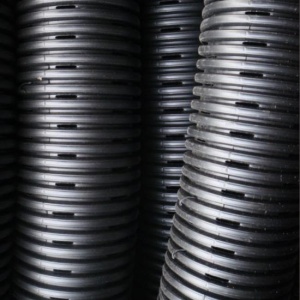
- For the same reason, dual walled perforated pipes with smooth internal walls are highly recommended to reduce the potential snagging of maintenance equipment.
- The recommended distances between clean outs is based on advice for filter beds in the Ontario Building Code[5]. However, the access capabilities of difference apparatus and contractors varies and designers are advised to take advice from maintenance operators in this matter.
Material specifications[edit]
Pipes[edit]

Perforated pipes are a common component of underdrains used in bioretention, permeable pavements, infiltration trenches and exfiltration systems.
Pipes should be manufactured in conformity with the latest standards by the Canadian Standards Association (CSA) or ASTM International.
- Perforated pipes should be continuously perforated, smooth interior HDPE or PVC.
- Wherever possible pipes should be ≥200 mm internal diameter to reduce potential of freezing and to facilitate push camera inspections and cleaning with jet nozzle equipment.
- Smooth interior facilitates inspection and maintenance activities; internal corrugations can cause cameras or hydrojetting apparatus to become snagged.
- A perforated pipe with many rectangular slots has better drainage characteristics than a pipe with similar open area provided by fewer circular holes [6].
- Non-perforated pipes should be used for conveyance of stormwater to and from the facility, including overflow. It is good practice to extend the solid pipe approximately 300 mm within the reservoir or practice to reduce the potential for native soil migration into the pipe.
Pipe with slotted perforations
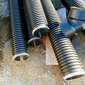
Perforated pipes awaiting installation, note the 45 degree couplings used to facilitate push camera inspection and jet nozzle cleaning.


See also: Flow through perforated pipe
Reservoir gravel[edit]
This article gives recommendations for aggregate to be used to store water for infiltration. This is usually called 'clear stone' at aggregate yards.
To see an analysis of Ontario Standard Specifications for granular materials, see OPSS aggregates.
For advice on decorative surface aggregates see Stone
Gravel used for underdrains in bioretention, infiltration trenches and chambers, and exfiltration trenches should be 20 or 50 mm, uniformly-graded, clean (maximum wash loss of 0.5%), crushed angular stone that has a porosity of 0.4[7].
The clean wash to prevent rapid accumulation of fines from the aggregate particles in the base of the reservoir. The uniform grading and the angularity are important to maintain pore throats and clear voids between particles. (i.e. achieve the porosity). Porosity and permeability are directly influenced by the size, gradation and angularity of the particles [8]. See jar test for on-site verification testing protocols.
Gravel with structural requirements should also meet the following criteria:
- Minimum durability index of 35
- Maximum abrasion of 10% for 100 revolutions and maximum of 50% for 500 revolutions
Standard specifications for the gradation of aggregates are maintained by ASTM D2940
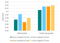
The highest porosity is found in uniformly graded aggregate, as there are no smaller particles to occupy the inter-particle pores. [8]
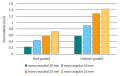
Higher permeability is found in larger, angular, uniformly graded aggregate. This is due to larger pore sizes and lower tortuosity. [8]


Choker layer[edit]

In bioretention systems a choker layer of ≥ 100 mm depth is the recommended method to prevent migration of finer filter media into the underlying storage reservoir aggregate. These same mid-sized granular materials are recommended for use in Stormwater planter underdrains and may be useful in the fine grading of foundations courses for permeable pavements.
Suitable materials include:
- High performance bedding (HPB)
- Clean, angular aggregate screened to between 6 and 10 mm. Widely available and designed specifically for drainage applications. Free from fines by definition.
- HL 6
- Is a clean, angular aggregate screened between 10 and 20 mm. Free from fines by definition.
- Pea Gravel
- Rounded natural aggregate, screened between 5 and 15 mm, and washed free from fines.
In most scenarios, a geotextile layer is unnecessary and has been associated with rapid decline and clogging in some circumstances. Geotextiles may be used to separate the underdrain from native soils on the vertical faces.
Alternative technologies[edit]
- Smart Drain is a polymer ribbon-like material with capillary drains on the underside; it's use has recently been demonstrated in bioretention[9]. It's low profile may make it particularly well suited to non-infiltrating practices, such as Stormwater planters.

Planting medium


It is recommended that the mixture comprises:
| Blend A: Drainage rate priority | Blend B: Water quality treatment priority | |
|---|---|---|
| Application | Impervious area to pervious area (I:P) ratio of 15:1 or greater |
|
| Proportions |
3 parts sand |
3 parts sand |
| Porosity | This mixture may be assumed to have a porosity of 0.4 unless demonstrated otherwise | This mixture may be assumed to have a porosity of 0.35 unless demonstrated otherwise |
Filter media should be obtained premixed from the vendor and meet all municipal, provincial and federal environmental standards. To minimize transportation-related environmental impacts, filter media should be obtained from local vendors and blended from locally sourced materials. Topsoil used to produce the mix should be passed through a 5 centimetre (2 inch) screen to remove large rocks, roots and other debris, while retaining soil peds. Samples of the filter media should be dried, ground and tested by a certified soil testing laboratory to ensure they meet the following specifications:
| Characteristic | Criterion | Recommended test method |
|---|---|---|
| Particle-size distribution (PSD) | < 25% silt- and clay-sized particles (smaller than 0.05 mm) combined; 3 to 12% clay-sized particles (0.002 mm or smaller) |
ASTM D6913/D6913M, Standard Test Methods for Particle-Size Distribution (Gradation) of Soils Using Sieve Analysis (pebble to sand fraction); and ASTM D7928, Standard Test Method for Particle-Size Distribution (Gradation) of Fine-Grained Soils Using the Sedimentation (Hydrometer) Analysis (silt and clay fraction). |
| Organic matter (OM) | 3 to 10% by dry weight | ASTM F1647, Standard Test Methods for Organic Matter Content of Athletic Field Rootzone Mixes. |
| Phosphorus, plant-available or extractable | 12 to 40 ppm | As measured by the 'Olsen' method for alkaline and calcareous soils (common in Ontario). Alternatives include 'Mehlich I or III', or 'Bray', which is better suited to acidic to slightly alkaline and non-calcareous soils. NB: Results from different test methods are not directly comparable.[10] |
| Cationic exchange capacity (CEC) | > 10 meq/100 g | ASTM D7503, Standard Test Methods for Measuring the Exchange Complex and Cation Exchange Capacity of Inorganic Fine-Grained Soils. |
| Hydraulic conductivity, saturated (Kf) | > 75 mm/h; Blend A > 25 mm/h; Blend B < 300 mm/h; Blend A and B |
ASTM D2434, Standard Test Method for Permeability of Granular Soils (Constant Head), when the sample is compacted to 85% of its maximum dry density in accordance with ASTM D698, Standard Test Methods for Laboratory Compaction Characteristics of Soil Using Standard Effort. |
Note that you may choose not to use particle-size distribution as a criterion for acceptance of a filter media blend, but saturated hydraulic conductivity should be one. While information on particle-size distribution and soil texture are useful in selecting plants, the disconnect between hydraulic conductivity and uniformity of gradation makes it far less important than measuring the saturated hydraulic conductivity directly[11]
Sand[edit]

- Coarse sand for LID construction shall be washed clean and free of toxic materials.
- The pH of the sand shall be ≤ 7.0.
- The coarse sand shall have a fineness modulus index between 2.8 and 3.1 according to ASTM C33/C33M, or otherwise meet the gradation below.
| Sieve | Percent passing |
|---|---|
| 9.5 mm | 100 |
| 4.75 mm (No.4) | 95 - 100 |
| 2.36 mm (No.8) | 80 - 100 |
| 1.18 mm (No.16) | 50 - 85 |
| 0.60 mm (No.30) | 25 - 50 |
| 0.30 mm (No.50) | 5 - 30 |
| 0.15 mm (No.100) | 0 - 10 |
| 0.075 mm (No.200) | ≤ 3 |
Topsoil[edit]
- Topsoil may be material that was stripped from the project site and stored in stockpiles for re-use, or material imported to the site from a supplier provided the physical and chemical characteristics are within acceptable ranges.
- Topsoil shall be in compliance with Ontario Regulation 153/04 Record of Site Condition standards for soil quality or as amended through Ontario Management of Excess Soil - A Guide for Best Management Practices.
- Soil laboratory reports shall certify the material to be suitable for re-use on residential, parkland, institutional, industrial, commercial, or community landscapes for the germination of seeds and the support of vegetative growth.
The factors to consider in determining if a topsoil is suitable for use as planting soil for a vegetated stormwater practice, or use in producing a bioretention filter media mixture include the following:
- Must be friable and capable of sustaining vigorous plant growth;
- Must be free from toxic material and roots, stones or debris over 50 mm (2") in diameter;
- Should not have been passed through sieves or screens smaller than 50 mm (2”) to avoid eliminating peds;
- Should have a Loamy Sand, Sandy Loam, Sandy Clay Loam, Loam or Silty Loam soil texture;
- For use as planting soil for a vegetated stormwater practice , the topsoil must contain a minimum of 5% organic matter by dry weight or be amended so, through addition of an organic soil conditioner;
- For use in producing bioretention filter media Blend B (water quality treatment priority), the topsoil must contain at least 9%, and not greater than 36% clay-sized particles and at least 2% organic matter by dry weight.
- Must have a pH of between 6.0 and 8.0;
- Must have a sodium absorption ratio less than 15;
- Must have a cationic exchange capacity greater than 10 milliequivalents per 100 grams (meq/100 g).
Specify that 4 litre samples of topsoil, from each source to be drawn upon, be provided to the consultant for visual inspection, along with topsoil quality test results from an accredited soil testing laboratory, or a quality assurance certificate from the supplier.
We recommend a planting soil or filter media depth of 300 mm to support grasses, 600 mm for shrubs and perennials, and 1000 mm for trees.
Organic component[edit]
This is the first big opportunity to manage phosphorus export from a bioretention or stormwater planter system. While compost is the most common choice, designers working in nutrient-sensitive receiving waters are encouraged to explore the alternatives listed below. Some of these materials may be combined 50:50 with compost to balance providing the nutrients required by the plants with limiting the potential for leaching of excess nutrients.
Compost[edit]
Compost is the most widely used organic component. It's use in bioretention facilities is well established and documented. In Ontario, compost should comply with mandatory Ontario Compost Quality Standards for Category 'AA'.[12] See Compost page for a summary of Category 'AA" compost standards. Compost should also be certified to meet quality parameters recommended under the Compost Council of Canada Compost Quality Alliance (CQA) program.[13] Low available phosphorus composts should always be sought for use in low impact development facilities, including bioretention. Low available phosphorus composts are typically created from feedstocks including yard, leaf, and wood waste, and excluding manures, biosolids, and food scraps.[14]
Organic component alternatives[edit]
Even low-phosphorus composts are known to export phosphorus over many years. The use of compost is not recommended in nutrient-sensitive watersheds where phosphorus pollution is a concern, or an additive to enhance nutrient retention of the media should also be included in the blend, or a layer be included above the stone reservoir, or a reactive media vault be included in the treatment train downstream of the bioretention (see Additive below for available options). There are a number of alternative sources of soil organic matter which have undergone field studies which have benefits and potential concerns:
| Material | Benefits | Concerns |
|---|---|---|
| Coconut coir[15] | Doesn't leach phosphorus | Must be imported |
| Wood chips | Doesn't leach phosphorus Promotes nitrogen removal from water |
|
| Peat moss | Doesn't leach phosphorus | Must be unsustainably extracted from natural wetlands |
| Shredded paper (e.g., Pittmoss) | Doesn't leach phosphorus Promotes denitrification |
Wood derivatives[edit]
The 2017 guidance from New Hampshire specifically rules against the inclusion of compost in their bioretention media.[16] Instead they recommend "Shredded wood, wood chips, ground bark, or wood waste; of uniform texture and free of stones, sticks". The use of wood chip has been common in New Hampshire for some time, in this 2006 thesis 20% wood chips (not characterized) were incorporated into all of the test cases to match current practices at the time. [17]
Shredded paper has been tested as an additional source of carbon and as an electron-donor to promote denitrification in a number of successful laboratory and field studies. <ref>
Additives[edit]
Typically these components would make up 5 to 10% by volume of the filter media mixture.
Design innovations to improve water quality treatment performance of filter media mixtures involve the incorporation of additives to enhance retention of reactive or dissolved pollutants. A number of granular amendments have been demonstrated to improve nutrient removal from discharge water in BMPs such as bioretention systems, stormwater planters, absorbent landscapes, sand filters or green roofs.
There are two primary processes involved, chemical precipitation and adsorption. Both mechanisms are ultimately finite, but have been shown in some cases to make significant improvements on the discharged water quality over several years. For instance, a two year STEP research study that compared standard bioretention media, to the same media amended with Sorbtive™ in one plot and iron enriched sand (aka red sand) in another showed statistically significant improvements in effluent phosphorus concentrations from the two media amended plots (STEP, 2019)[18].
Determining when additive enhanced filter media needs replacing or maintenance represents a new challenge for stormwater asset managers, as there are no suitable visual indicators. Erickson et al. (2018) suggest effluent sampling and laboratory testing to identify when enhanced filter media pollutant retention is waning, or periodic sampling and batch (laboratory) testing of filter media to directly measure its capacity to retain the targeted pollutants[19]. Periodic replacement of filter media at inlet locations should be considered as an operation and maintenance best practice to maintain treatment performance.
In our effort to make this guide as functional as possible, we have decided to include proprietary systems and links to manufacturers websites.
Inclusion of such links does not constitute endorsement by the Sustainable Technologies Evaluation Program.
Lists are ordered alphabetically; link updates are welcomed using the form below.
| Material | Benefits | Potential concerns |
|---|---|---|
| Biochar | Renewable Enhances soil aggregation, water holding capacity and organic carbon content |
Currently expensive Energy intensive to produce Some sources say ineffective for phosphorus removal |
| Bold & GoldTM | Documented total phosphorus removal of up to 71%[20] | Proprietary |
| Iron filings or Zero valent iron (ZVI) | Proven phosphorus retention Retained phosphorus is stable |
May harm plants[21] Removal efficiency declines with increased concentration of incoming phosphorus |
| Red sand or Iron-enriched sand | Proven phosphorus removal Also removes TSS |
Poor orthophosphate removal in hypoxic or anoxic conditions |
| Smart SpongeTM | Removes phosphorus, as well as TSS, fecal coliform bacteria and heavy metals Non-leaching |
1-3 year lifespan, after which the product is removed as solid waste Proprietary |
| Sorbtive MediaTM | High phosphorus removal efficiency | Proprietary |
| Water treatment residuals | Waste product reuse | Quality control (capabilities depend on source, treatment methods, storage time) |
References[edit]
Plant list
- ↑ Ministry of Transportation. 2010. Foundation Frost Penetration Depths for Northern Ontario. OPSD 3090.100. Nov 2010. Rev.1. https://www.library.mto.gov.on.ca/SydneyPLUS/TechPubs/Portal/tp/opsViews.aspx
- ↑ Ministry of Transportation. 2010. Foundation Frost Penetration Depths for Southern Ontario. OPSD 3090.101. Nov 2010. Rev.1. https://www.library.mto.gov.on.ca/SydneyPLUS/TechPubs/Portal/tp/opsViews.aspx
- ↑ Province of Ontario. (2018). O. Reg. 332/12: BUILDING CODE. Retrieved February 23, 2018, from https://www.ontario.ca/laws/regulation/120332
- ↑ Province of Ontario. (2022). O. Reg. 332/12: BUILDING CODE. Retrieved February 23, 2018, from https://www.ontario.ca/laws/regulation/120332
- ↑ Province of Ontario. (2018). O. Reg. 332/12: BUILDING CODE. Retrieved February 23, 2018, from https://www.ontario.ca/laws/regulation/120332
- ↑ Hazenberg, G., and U. S. Panu (1991), Theoretical analysis of flow rate into perforated drain tubes, Water Resour. Res., 27(7), 1411–1418, doi:10.1029/91WR00779.
- ↑ Porosity of Structural Backfill, Tech Sheet #1, Stormtech, Nov 2012, http://www.stormtech.com/download_files/pdf/techsheet1.pdf accessed 16 October 2017
- ↑ 8.0 8.1 8.2 Judge, Aaron, "Measurement of the Hydraulic Conductivity of Gravels Using a Laboratory Permeameter and Silty Sands Using Field Testing with Observation Wells" (2013). Dissertations. 746. http://scholarworks.umass.edu/open_access_dissertations/746
- ↑ Redahegn Sileshi; Robert Pitt, P.E., M.ASCE; and Shirley Clark, P.E., M.ASCE Performance Evaluation of an Alternative Underdrain Material for Stormwater Biofiltration Systems, Journal of Sustainable Water in the Built Environment, 4(2), May 2018 https://doi.org/10.1061/JSWBAY.0000845
- ↑ Sawyer JE, Mallarino AP. Differentiating and Understanding the Mehlich 3, Bray, and Olsen Soil Phosphorus Tests 1. http://www.agronext.iastate.edu/soilfertility/info/mnconf11_22_99.pdf. Accessed August 1, 2017.
- ↑ CRC for Water Sensitive Cities. (2015). Adoption Guidelines for Stormwater Biofiltration Systems: Appendix C - Guidelines for filter media in stormwater biofiltration systems.
- ↑ Ontario Ministry of the Environment and Climate Change (OMOECC). 2012. Ontario Compost Quality Standards, July 25, 2012. PIBS 8412. Queen’s Printer of Ontario, Toronto, ON. https://www.ontario.ca/page/ontario-compost-quality-standards.
- ↑ A & L Canada Laboratories. 2004. Compost Management Program. London, ON. http://www.alcanada.com/index_htm_files/compost_handbook.pdf.
- ↑ Hurley S, Shrestha P, Cording A. Nutrient Leaching from Compost: Implications for Bioretention and Other Green Stormwater Infrastructure. J Sustain Water Built Environ. 2017;3(3):4017006. doi:10.1061/JSWBAY.0000821.
- ↑ Rheaume, A., Hinman, C., and Ahearn, D. (2015). “A Synthesis of Bioretention Research in Pacific Northwest.” Herrera, <http://www.modularwetlands.com/new/wp-content/uploads/2015/11/2-Bioretention-Synthesis-2015-DAhearn.pdf>
- ↑ UNHSC Bioretention Soil Specification. (2017). Retrieved from https://www.unh.edu/unhsc/sites/default/files/media/unhsc_bsm_spec_2-28-17_0.pdf
- ↑ Stone, R. M. (2013). Evaluation and Optimization of Bioretention Design for Nitrogen and Phosphorus Removal. University of New Hampshire. Retrieved from https://www.unh.edu/unhsc/sites/unh.edu.unhsc/files/STONE THESIS FINAL.pdf
- ↑ STEP. 2019. Improving nutrient retention in bioretention. Technical Brief. Accessed: https://sustainabletechnologies.ca/app/uploads/2019/06/improving-nutrient-retention-in-bioretention-tech-brief.pdf
- ↑ Erickson, A.J., Taguchi, V.J., Gulliver, J.S. 2018. The Challenge of Maintaining Stormwater Control Measures: A Synthesis of Recent Research and Practitioner Experience. Sustainability. 2018, 10, 3666. https://www.mdpi.com/2071-1050/10/10/3666
- ↑ Hood A, Chopra M, Wanielista M. Assessment of Biosorption Activated Media Under Roadside Swales for the Removal of Phosphorus from Stormwater. Water. 2013;5(1):53-66. doi:10.3390/w5010053.
- ↑ Logsdon SD, Sauer PA. Iron Filings Cement Engineered Soil Mix. Agron J. 2016;108(4):1753. doi:10.2134/agronj2015.0427.