Difference between revisions of "Bioretention"
Kyle menken (talk | contribs) |
Dean Young (talk | contribs) |
||
| (361 intermediate revisions by 10 users not shown) | |||
| Line 1: | Line 1: | ||
| − | [[ | + | <imagemap> |
| − | [[ | + | File:Bioretention Full Partial infiltration placementswap.png|thumb|600px|'''[[Bioretention: Partial infiltration|Partial infiltration bioretention]]''' cell draining a parking lot. Designs for this type of LID practice vary, but typically include a water storage reservoir, optional choker layer, filter media layer, mulch and vegetation. Other design variations include [[Bioretention: Full infiltration|'''full infiltration''']] and [[Stormwater planters|'''no infiltration''']] configurations which can be explored with their own image maps. <span style="color:red">'''''Note''': The following is an "image map", feel free to explore the image with your cursor and click on highlighted labels that appear to take you to corresponding pages on the Wiki.''</span> |
| + | |||
| + | |||
| + | |||
| + | |||
| + | rect 1295 2828 1342 3128 [[Underdrains|Underdrain Access Structure]] | ||
| + | rect 1296 1423 1348 1478 [[Underdrains|Underdrain Access Structure]] | ||
| + | rect 1293 3128 1346 3178 [[Underdrains|Underdrain]] | ||
| + | rect 1112 3181 1169 3250 [[Digital technologies|Water Level Sensor]] | ||
| + | rect 1134 3187 1159 3246 [[Digital technologies|Water Level Sensor]] | ||
| + | rect 1126 2838 1163 3187 [[Wells|Monitoring Well]] | ||
| + | rect 1116 1437 1163 1480 [[Wells|Monitoring Well]] | ||
| + | rect 1295 3183 1348 3254 [[Bioretention: Internal water storage|Internal Water Storage]] | ||
| + | rect 939 1415 1011 1482 [[Overflow|Overflow Outlet]] | ||
| + | rect 956 2845 1017 3177 [[Overflow|Overflow Outlet]] | ||
| + | rect 935 3229 1012 3285 [[Overflow|Overflow Outlet Pipe]] | ||
| + | poly 866 326 866 241 1386 241 1386 416 1392 683 1337 620 1270 579 1278 410 1241 339 1078 326 1045 398 1049 400 992 355 [[Mulch|Mulch]] | ||
| + | poly 870 685 868 610 1000 567 1004 632 [[Mulch|Mulch]] | ||
| + | poly 868 1028 966 1081 1021 1370 864 1485 870 1283 868 1211 870 1136 [[Mulch|Mulch]] | ||
| + | poly 990 1397 1045 1482 1110 1485 1111 1421 [[Mulch|Mulch]] | ||
| + | poly 1214 1389 1263 1419 1339 1440 1390 1446 1384 1491 1161 1497 [[Mulch|Mulch]] | ||
| + | poly 1292 1062 1386 1032 1384 1164 1249 1209 [[Mulch|Mulch]] | ||
| + | rect 1027 379 870 575 [[Stone|Erosion Control - Stone]] | ||
| + | rect 1241 1223 1392 1432 [[Stone|Erosion Control - Stone]] | ||
| + | rect 815 389 868 540 [[Curb cuts|Curb Cut]] | ||
| + | rect 1398 1234 1441 1378 [[Curb cuts|Curb Cut]] | ||
| + | rect 862 685 1388 1038 [[Trees: List|Tree]] | ||
| + | rect 1068 351 1245 648 [[Plant lists|Vegetation]] | ||
| + | rect 1007 1089 1235 1399 [[Plant lists|Vegetation]] | ||
| + | rect 854 1652 1408 2651 [[Trees: List|Tree]] | ||
| + | rect 1064 2684 1227 2822 [[Plant lists|Vegetation]] | ||
| + | rect 862 2863 955 2940 [[Flow through media|Ponding Depth]] | ||
| + | rect 1017 2902 1119 2942 [[Mulch|Mulch]] | ||
| + | rect 1164 2900 1398 2938 [[Mulch|Mulch]] | ||
| + | rect 864 2943 955 3079 [[Bioretention: Filter media|Filter Media]] | ||
| + | rect 1023 2941 1111 3083 [[Bioretention: Filter media|Filter Media]] | ||
| + | rect 1168 2938 1392 3081 [[Bioretention: Filter media|Filter Media]] | ||
| + | rect 866 3083 953 3116 [[Choker layer|Choker Layer]] | ||
| + | rect 1021 3079 1110 3116 [[Choker layer|Choker Layer]] | ||
| + | rect 1168 3085 1386 3116 [[Choker layer|Choker Layer]] | ||
| + | rect 868 3120 955 3185 [[Reservoir aggregate|Clear Stone / Aggregate]] | ||
| + | rect 1023 3114 1113 3189 [[Reservoir aggregate|Clear Stone / Aggregate]] | ||
| + | rect 1170 3116 1388 3191 [[Reservoir aggregate|Clear Stone / Aggregate]] | ||
| + | rect 1045 3252 1363 3309 [[Soil groups|Uncompacted Subgrade Soil]] | ||
| + | rect 900 3289 1047 3309 [[Soil groups|Uncompacted Subgrade Soil]] | ||
| + | |||
| + | |||
| + | </imagemap> | ||
| + | |||
| + | [[Bioretention]] refers to vegetated stormwater practices that temporarily store roof and pavement runoff in depressed planting beds or vertical-walled structures. | ||
| + | Depending on native soil infiltration rate and physical constraints, the facility may be designed without an underdrain for full infiltration, with an underdrain for partial infiltration, or with an impermeable liner and underdrain for no infiltration, "filtration only" (i.e., a stormwater planter or biofilter) design. | ||
| + | Bioretention can be adapted to fit into many different development contexts and provides a convenient area for snow storage and treatment. | ||
| + | <br> | ||
| + | <br> This article is about full and partial infiltration design variations that capture and infiltrate some or all of the stormwater received. | ||
| + | <br> For simple systems, without underdrains or storage reservoirs (typically found in residential settings), see [[Rain gardens]]. | ||
| + | <br> For linear systems that have a gradually sloping filter media bed and can convey surface flow, but are otherwise similar to bioretention, see [[Bioswales]]. | ||
| + | <br> For planted systems that are lined and do not infiltrate water, see [[Stormwater planters]]. | ||
| + | |||
| + | |||
{{TOClimit|2}} | {{TOClimit|2}} | ||
| − | + | ||
| − | |||
| − | |||
| − | |||
==Overview== | ==Overview== | ||
| − | Bioretention systems may be the most well recognized form of [[low impact development]] (LID). They can fit into any style of landscape and | + | Bioretention systems may be the most well-recognized form of [[low impact development]] (LID). They can fit into any style of landscape and utilize all of the stormwater treatment mechanisms: sedimentation, [[infiltration]], filtration, attenuation and [[evapotranspiration]]. |
{{textbox|Bioretention is an ideal technology for: | {{textbox|Bioretention is an ideal technology for: | ||
| − | *Fitting functional vegetation into urban landscapes | + | *Fitting multi-functional vegetation into urban landscapes |
*Treating runoff collected from nearby impervious surfaces}} | *Treating runoff collected from nearby impervious surfaces}} | ||
| + | |||
| + | Take a look at the downloadable Bioretention Factsheet below for a .pdf overview of this LID Best Management Practice: | ||
| + | |||
| + | {{Clickable button|[[File:Bioretention.png|125 px|link=https://wiki.sustainabletechnologies.ca/images/5/5a/LID_poster_-_bioretention_-_vfinal2.pdf]]}} | ||
| + | |||
| + | |||
'''The fundamental components of a bioretention cell are:''' | '''The fundamental components of a bioretention cell are:''' | ||
| − | *A | + | *[[Inlets| Inlets]] which may be curb openings (e.g. modified curbs, spillways), pipes, road or side inlet catchbasins, trench drains or other pre-fabricated inlet structures; |
| − | *A | + | *A surface ponding area defined by landscaped side slopes or hardscape structures and the invert elevation of the overflow outlet structure; |
| − | *[[ | + | *A filter bed containing [[Bioretention: Filter media| filter media]]; |
| + | *A filter bed surface cover layer (e.g. [[mulch]] and [[stone]]); | ||
| + | *[[Plant lists|Plants]], and; | ||
| + | *An [[Overflow| overflow outlet]] to limit surface ponding and safely convey excess flow to a downstream storm sewer or the next BMP in the treatment train. | ||
'''Additional components may include:''' | '''Additional components may include:''' | ||
| − | *An [[underdrain]] to redistribute or remove excess water | + | *An [[underdrain]] to redistribute or remove excess water and access structures or standpipes for periodic inspection and flushing; |
| − | *An [[Liner| | + | *An [[Bioretention: Internal water storage| internal water storage reservoir]] composed of a [[reservoir aggregate]] layer, and may include embedded void-forming structures to minimize depth and conserve aggregate, and organic material derived from untreated wood (aids in dissolved nitrogen removal); |
| + | *[[Wells|Monitoring wells]] installed to the base and screened in the [[underdrain]] aggregate to verify and track [[Drainage time|drainage time]]; and | ||
| + | *Filter media [[additives]] intended to enhance retention of nutrients, metals, petroleum hydrocarbons and/or bacteria. | ||
| + | *[[Liner|Impervious liner]] can be installed if the bioretention facility is designed as a [[stormwater planter]] and is in close proximity to buildings or in a tight space in an urbanized environment or if located near pollution hotspots/contaminated soils, or in areas with higher than normal water tables. | ||
==Planning considerations== | ==Planning considerations== | ||
| − | + | ||
| − | |||
| − | |||
| − | |||
| − | |||
| − | |||
| − | |||
| − | |||
| − | |||
===Infiltration=== | ===Infiltration=== | ||
| − | Some form of stormwater landscaping (bioretention) can be | + | Some form of stormwater landscaping (bioretention) can be integrated into most spaces. Although there are some [[Infiltration#Constraints|constraints]] to infiltrating water, it is preferable to do so where possible. |
| − | + | Designing bioretention without an underdrain is highly desirable wherever the soils permit infiltration at a rate which is great enough to empty the facility between storm events. Volume reduction is achieved primarily through infiltration to the underlying soils, with some evapotranspiration. As there is no outflow from this BMP under normal operating conditions, it is particularly useful in areas where nutrient management is a concern to the watershed. | |
| − | |||
| − | |||
| − | |||
| − | |||
| − | |||
| − | |||
| − | + | Bioretention with an [[underdrain]] is a popular choice in areas with 'tighter' soils where infiltration rates are < 15 mm/hr. Including a perforated [[pipe]] in the [[reservoir aggregate]] layer helps to empty the facility between storm events, which is particularly useful in areas with [[low permeability soils]]. The drain discharges to a downstream point, which could be an underground [[infiltration trench]] or [[chamber]] facility. Volume reduction is gained through infiltration and [[evapotranspiration]]. By raising the outlet of the discharge pipe the bottom portion of the BMP can only drain through infiltration, creating an [[Bioretention: Internal_water_storage| internal water storage reservoir]]. This creates a fluctuating anaerobic/aerobic environment which promotes denitrification. Increasing the period of storage has benefits for promoting infiltration, but also improves water quality for catchments impacted with nitrates. A complimentary technique is to include fresh wood mulch in the storage [[Reservoir aggregate| reservoir aggregate]], which fosters denitrifying biological processes. | |
| − | * | + | |
| − | * | + | For more information about constraints to infiltration practices, and approaches and tools for identifying and designing within them see [[Infiltration]]. |
| − | * | + | |
| − | ===Overflow | + | Where infiltration is infeasible or not permitted, but the design calls for planted landscaping, try a [[stormwater planter]] instead. |
| + | |||
| + | ===Native Soil=== | ||
| + | Bioretention can be constructed over any soil type, but hydrologic soil group A and B are best for achieving water balance objectives. Facilities designed to infiltrate water should be located on portions of the site with the highest infiltration rates. For infiltration rates <15 mm/h an underdrain is recommended. Native soil infiltration rate at the proposed location and depth should be confirmed through in-situ measurements of hydraulic conductivity under field saturated conditions. See [[Design infiltration rate]] for further guidance. | ||
| + | |||
| + | ===Wellhead Protection=== | ||
| + | Facilities receiving road or parking lot runoff should not be located within the 2 year time-of-travel Wellhead Protection Area for municipal drinking water supply wells (refer to applicable drinking water source protection plan for details). | ||
| + | |||
| + | ===Available Space=== | ||
| + | *The principles of bioretention can be applied in any scenario where planting or vegetation would normally be found. | ||
| + | *In the conceptual design stage it is recommended to reserve approximately 10 to 20% of the contributing drainage area for the bioretention facility footprint. | ||
| + | *For optimal performance recommended ratios of impervious drainage area to pervious facility footprint area (I:P area ratio) range from 5:1 on low permeability soils (HSG C and D) to 20:1 on high permeability soils (HSG A and B). | ||
| + | *Minimum bioretention facility footprint area (i.e., filter bed area) is based on the design storm runoff volume and effective surface ponding depth. | ||
| + | *Bioretention cells work best when distributed, so that no one facility receives runoff from more than 0.8 Ha, although there is a trade-off to be considered regarding distributed collection and treatment versus ease of maintenance. | ||
| + | *Bioretention can be almost any shape, from having very curvilinear, soft edges with variable depth, to angular, hard-edged and uniform depth. | ||
| + | *Linear trench or swale geometries will drain faster than round or square shapes because they have larger perimeters. | ||
| + | *For ease of construction and to ensure that the vegetation has adequate space, cells should be no narrower than 0.6 m at any point. | ||
| + | *The maximum width of a facility is determined by the reach of the excavator, which should not be tracked into the cell. | ||
| + | |||
| + | ===Site Topography=== | ||
| + | Contributing slopes should be 1 to 5%. The filter bed surface should be flat to allow flow to spread out. A stepped, multi-cell design can also be used. | ||
| + | ===Available Head=== | ||
| + | If an underdrain is used, then an elevation difference of 1 to 1.5 m is needed between the inverts of the inlet and the downstream storm sewer. | ||
| + | ===Water Table=== | ||
| + | Maintaining a separation of 1 m between the elevations of the bottom of the practice and the seasonally high water table, or top of bedrock, is recommended. Lesser or greater values may be considered based on [[groundwater |groundwater mounding analysis]]. | ||
| + | |||
| + | ===Pollution Hot Spot Runoff=== | ||
| + | To prevent groundwater contamination, runoff from pollution hot spots should not be treated by bioretention facilities designed for full or partial infiltration. No infiltration, "filtration only" facilities (with an impermeable liner) can be used. | ||
| + | |||
| + | ===Proximity to Underground Utilities=== | ||
| + | Designers should consult local utility design guidance for the horizontal and vertical clearances required between storm drains, ditches, and surface water bodies. | ||
| + | ===[[Karst]]=== | ||
| + | Infiltration designs are unsuitable in areas of known or implied [[Karst |karst]] topography and geologic formations. | ||
| + | |||
| + | ===Overhead Wires=== | ||
| + | Check to ensure whether the future tree canopy height in the bioretention area will interfere with existing overhead wires. | ||
| + | |||
| + | ===Setbacks From Buildings=== | ||
| + | If an impermeable liner is used, no setback is needed, although designing to maintain drainage away from the building is crucial. Where no liner is used, a setback of 4 m from the building foundations should be applied. | ||
| + | ===Context=== | ||
| + | In single family residential sites [[Rain gardens|rain gardens]] most often take the form of a soft edged, traditional perennial planting bed. | ||
| + | As many private industrial, commercial and institutional sites have landscaping around their [[Bioretention: Parking lots| parking lots]], bioretention is an increasingly popular choice to manage stormwater in these contexts. | ||
| + | |||
| + | ===Streetscapes=== | ||
| + | Bioretention is a popular choice for making urban green space work harder. Design configurations include extending the cells to accommodate shade trees, and using retrofit opportunities to create complete streets with traffic calming and curb extensions or 'bump outs'. See [[Bioretention: Streetscapes]] | ||
| + | |||
| + | ===Parkland and Natural Areas=== | ||
| + | Naturalized landscaping and soft edges can make a bioretention facility 'disappear' into green space surroundings. In some scenarios, a larger bioretention (50 - 800 m<sup>2</sup>) cell may be used as an end-of-pipe facility treating both sheet flow and concentrated flow before it enters an adjacent water course. In these larger installations care must be made in the design to distribute the inflow, preventing erosion and maximizing infiltration. | ||
| + | |||
| + | |||
| + | For a table summarizing information on planning considerations and site constraints see [[Site considerations]]. | ||
| + | |||
| + | ==Design== | ||
| + | {|class="wikitable" | ||
| + | |+ Optimizing bioretention for water quality | ||
| + | |- | ||
| + | !style="background: darkcyan; color: white"|Poor design choice: <br> Limits outflow water quality | ||
| + | !style="background: darkcyan; color: white"|Better design choice: <br> Improves outflow water quality | ||
| + | |- | ||
| + | |Single large cell design||Several smaller distributed or connected cells | ||
| + | |- | ||
| + | |Single concentrated inflow||Forebays or distributed flow | ||
| + | |- | ||
| + | |No pretreatment||Pretreatment provided as part of inlet design | ||
| + | |- | ||
| + | |Filter bed < 0.5 m||Filter bed > 0.75 m | ||
| + | |- | ||
| + | |Filter media Plant-Available Phosphorus > 40 ppm||Filter media Plant-Available Phosphorus < 40 ppm | ||
| + | |- | ||
| + | |Filter media is predominantly sand||Filter media is a mixture of sand, topsoil and organic material | ||
| + | |- | ||
| + | |Surface covered with turf grass and stone||Surface covered with mulch and dense, deeply rooting vegetation | ||
| + | |- | ||
| + | |Internal water storage reservoir not included in underdrain design||Internal water storage reservoir included in underdrain design | ||
| + | |} | ||
| + | ===Design Variations=== | ||
| + | |||
| + | The figures below illustrate three design variations for a parking lot bioretention cell that differ according to whether or not drainage via infiltration into underlying native soils is to be promoted (i.e., lined or unlined) and their outlet configuration (i.e., with or without an underdrain and location of the perforated pipe in the cross-section). Full infiltration design does not include an underdrain and is suitable on highly permeable soils (>15 mm/hr infiltration rate) and residential rain gardens. No infiltration or "filtration only" designs feature an impermeable liner and underdrain and are suitable on all soil types. Partial infiltration design, that includes an underdrain and internal water storage reservoir is recommended where native soil infiltration rate is less than 15 mm/hr and is the most common. All the figures are image map drawings from the following pages to compare side-by-side the differences between varying configurations. | ||
| + | <br> | ||
| + | <br> | ||
| + | <imagemap> | ||
| + | File:Bioretention Full infiltration placementswap.png|thumb|left|400px|[[Bioretention: Full infiltration|'''Full infiltration bioretention''']] cell draining a parking lot. This design variation includes a surface overflow pipe/structure to allow excess water to leave the practice. A monitoring well is included so drainage performance can be evaluated over its operating lifespan. <small><span style="color:red">'''''Note''': The following is an "image map", feel free to explore the image with your cursor and click on highlighted labels that appear to take you to corresponding pages on the Wiki.''</span></small> | ||
| + | |||
| + | rect 1278 2868 1335 3149 [[Bioretention: Internal water storage|Internal Water Storage]] | ||
| + | rect 1129 3088 1159 3145 [[Digital technologies|Water Level Sensor]] | ||
| + | rect 1113 1434 1162 1487 [[Wells|Monitoring Well]] | ||
| + | rect 1129 2835 1162 3072 [[Wells|Monitoring Well]] | ||
| + | rect 1047 3147 1359 3225 [[Soil groups|Uncompacted subgrade soil]] | ||
| + | rect 898 3147 933 3225 [[Soil groups|Uncompacted subgrade soil]] | ||
| + | poly 870 241 866 322 953 333 1017 371 1045 400 1078 322 1129 312 1182 316 1235 328 1388 245 1263 245 1388 247 1155 243 [[Mulch|Mulch]] | ||
| + | poly 874 604 1021 573 1004 632 870 690 [[Mulch|Mulch]] | ||
| + | rect 1384 255 1266 602 [[Mulch|Mulch]] | ||
| + | rect 866 1034 990 1406 [[Mulch|Mulch]] | ||
| + | rect 1300 1061 1392 1171 [[Mulch|Mulch]] | ||
| + | rect 864 359 1015 585 [[Stone|Erosion Control - Stone]] | ||
| + | rect 1257 1206 1394 1420 [[Stone|Erosion Control - Stone]] | ||
| + | rect 813 382 862 530 [[Curb cuts|Curb Cut]] | ||
| + | rect 1396 1240 1439 1379 [[Curb cuts|Curb Cut]] | ||
| + | rect 862 687 1402 1034 [[Trees: List|Tree]] | ||
| + | rect 1066 355 1253 628 [[Plant lists|Vegetation]] | ||
| + | rect 1033 1100 1237 1406 [[Plant lists|Vegetation]] | ||
| + | rect 837 1653 1427 2609 [[Trees: List|Tree]] | ||
| + | rect 1047 2687 1245 2895 [[Plant lists|Vegetation]] | ||
| + | rect 866 2862 960 2938 [[Flow through media|Ponding Depth]] | ||
| + | rect 1019 2903 1272 2936 [[Mulch|Mulch]] | ||
| + | rect 1310 2901 1400 2936 [[Mulch|Mulch]] | ||
| + | rect 1021 2934 1266 3140 [[Bioretention: Filter media|Filter Media]] | ||
| + | rect 1312 2936 1363 3138 [[Bioretention: Filter media|Filter Media]] | ||
| + | rect 939 1416 1019 1485 [[Overflow|Overflow Outlet]] | ||
| + | rect 960 2846 1019 3215 [[Overflow|Overflow Outlet]] | ||
| + | poly 982 3227 941 3144 917 3160 953 3217 970 3219 1015 3227 1059 3152 1031 3148 1023 3191 1064 3176 [[Reservoir aggregate|Clear Stone / Aggregate]] | ||
| + | |||
| + | |||
| + | </imagemap> | ||
| + | |||
| + | |||
| + | <imagemap> | ||
| + | File:Bioretention Full Partial infiltration placementswap.png|thumb|right|400px|[[Bioretention: Partial infiltration|'''Partial infiltration bioretention cell''']] draining a parking lot. This design variation includes an underdrain and surface overflow pipes that allow excess water to leave the practice, along with a monitoring well to monitor drainage performance. <small><span style="color:red">'''''Note''': The following is an "image map", feel free to explore the image with your cursor and click on highlighted labels that appear to take you to corresponding pages on the Wiki.''</span></small> | ||
| + | |||
| + | rect 1134 3187 1159 3246 [[Digital technologies|Water Level Sensor]] | ||
| + | rect 1295 2828 1342 3128 [[Underdrains|Underdrain Access Structure]] | ||
| + | rect 1296 1423 1348 1478 [[Underdrains|Underdrain Access Structure]] | ||
| + | rect 1293 3128 1346 3178 [[Underdrains|Underdrain]] | ||
| + | rect 1134 3187 1159 3246 [[Digital technologies|Water Level Sensor]] | ||
| + | rect 1126 2838 1163 3187 [[Wells|Monitoring Well]] | ||
| + | rect 1116 1437 1163 1480 [[Wells|Monitoring Well]] | ||
| + | rect 1295 3183 1348 3254 [[Bioretention: Internal water storage|Internal Water Storage]] | ||
| + | rect 939 1415 1011 1482 [[Overflow|Overflow Outlet]] | ||
| + | rect 956 2845 1017 3177 [[Overflow|Overflow Outlet]] | ||
| + | rect 935 3229 1012 3285 [[Overflow|Overflow Outlet Pipe]] | ||
| + | poly 866 326 866 241 1386 241 1386 416 1392 683 1337 620 1270 579 1278 410 1241 339 1078 326 1045 398 1049 400 992 355 [[Mulch|Mulch]] | ||
| + | poly 870 685 868 610 1000 567 1004 632 [[Mulch|Mulch]] | ||
| + | poly 868 1028 966 1081 1021 1370 864 1485 870 1283 868 1211 870 1136 [[Mulch|Mulch]] | ||
| + | poly 990 1397 1045 1482 1110 1485 1111 1421 [[Mulch|Mulch]] | ||
| + | poly 1214 1389 1263 1419 1339 1440 1390 1446 1384 1491 1161 1497 [[Mulch|Mulch]] | ||
| + | poly 1292 1062 1386 1032 1384 1164 1249 1209 [[Mulch|Mulch]] | ||
| + | rect 1027 379 870 575 [[Stone|Erosion Control - Stone]] | ||
| + | rect 1241 1223 1392 1432 [[Stone|Erosion Control - Stone]] | ||
| + | rect 815 389 868 540 [[Curb cuts|Curb Cut]] | ||
| + | rect 1398 1234 1441 1378 [[Curb cuts|Curb Cut]] | ||
| + | rect 862 685 1388 1038 [[Trees: List|Tree]] | ||
| + | rect 1068 351 1245 648 [[Plant lists|Vegetation]] | ||
| + | rect 1007 1089 1235 1399 [[Plant lists|Vegetation]] | ||
| + | rect 854 1652 1408 2651 [[Trees: List|Tree]] | ||
| + | rect 1064 2684 1227 2822 [[Plant lists|Vegetation]] | ||
| + | rect 862 2863 955 2940 [[Flow through media|Ponding Depth]] | ||
| + | rect 1017 2902 1119 2942 [[Mulch|Mulch]] | ||
| + | rect 1164 2900 1398 2938 [[Mulch|Mulch]] | ||
| + | rect 864 2943 955 3079 [[Bioretention: Filter media|Filter Media]] | ||
| + | rect 1023 2941 1111 3083 [[Bioretention: Filter media|Filter Media]] | ||
| + | rect 1168 2938 1392 3081 [[Bioretention: Filter media|Filter Media]] | ||
| + | rect 866 3083 953 3116 [[Choker layer|Choker Layer]] | ||
| + | rect 1021 3079 1110 3116 [[Choker layer|Choker Layer]] | ||
| + | rect 1168 3085 1386 3116 [[Choker layer|Choker Layer]] | ||
| + | rect 868 3120 955 3185 [[Reservoir aggregate|Clear Stone / Aggregate]] | ||
| + | rect 1023 3114 1113 3189 [[Reservoir aggregate|Clear Stone / Aggregate]] | ||
| + | rect 1170 3116 1388 3191 [[Reservoir aggregate|Clear Stone / Aggregate]] | ||
| + | rect 1045 3252 1363 3309 [[Soil groups|Uncompacted Subgrade Soil]] | ||
| + | rect 900 3289 1047 3309 [[Soil groups|Uncompacted Subgrade Soil]] | ||
| + | |||
| + | </imagemap> | ||
| + | |||
| + | <imagemap> | ||
| + | File:Bioretention No infiltration placementswap.png|thumb|center|400px|[[Stormwater planters|'''Stormwater planter / No infiltration bioretention''' ]] cell draining a parking lot. This design variation includes an impermeable liner, an underdrain and surface overflow pipes to allow excess water to leave the practice. <small><span style="color:red">'''''Note''': The following is an "image map", feel free to explore the image with your cursor and click on highlighted labels that appear to take you to corresponding pages on the Wiki.''</span></small> | ||
| + | |||
| + | rect 1288 1419 1353 1483 [[Underdrains|Underdrain Access Structure]] | ||
| + | rect 1290 2822 1345 3140 [[Underdrains|Underdrain Access Structure]] | ||
| + | rect 1288 3142 1345 3191 [[Underdrains|Underdrain]] | ||
| + | poly 866 326 866 241 1386 241 1386 416 1392 683 1337 620 1270 579 1278 410 1241 339 1078 326 1045 398 1049 400 992 355 [[Mulch|Mulch]] | ||
| + | poly 870 685 868 610 1000 567 1004 632 [[Mulch|Mulch]] | ||
| + | poly 868 1028 966 1081 1021 1370 864 1485 870 1283 868 1211 870 1136 [[Mulch|Mulch]] | ||
| + | poly 990 1397 1045 1482 1110 1485 1111 1421 [[Mulch|Mulch]] | ||
| + | poly 1214 1389 1263 1419 1339 1440 1390 1446 1384 1491 1161 1497 [[Mulch|Mulch]] | ||
| + | poly 1292 1062 1386 1032 1384 1164 1249 1209 [[Mulch|Mulch]] | ||
| + | rect 1027 379 870 575 [[Stone|Erosion Control - Stone]] | ||
| + | rect 1241 1223 1392 1432 [[Stone|Erosion Control - Stone]] | ||
| + | rect 815 389 868 540 [[Curb cuts|Curb Cut]] | ||
| + | rect 1398 1234 1441 1378 [[Curb cuts|Curb Cut]] | ||
| + | rect 862 685 1388 1038 [[Trees: List|Tree]] | ||
| + | rect 1068 351 1245 648 [[Plant lists|Vegetation]] | ||
| + | rect 1007 1089 1235 1399 [[Plant lists|Vegetation]] | ||
| + | rect 939 1415 1011 1482 [[Overflow|Overflow Outlet]] | ||
| + | rect 854 1652 1408 2651 [[Trees: List|Tree]] | ||
| + | rect 1064 2684 1227 2822 [[Plant lists|Vegetation]] | ||
| + | rect 862 2863 955 2940 [[Flow through media|Ponding Depth]] | ||
| + | rect 1017 2902 1119 2942 [[Mulch|Mulch]] | ||
| + | rect 1164 2900 1398 2938 [[Mulch|Mulch]] | ||
| + | rect 960 3126 1019 3175 [[Overflow|Overflow Outlet Pipe]] | ||
| + | rect 956 2845 1017 3177 [[Overflow|Overflow Outlet]] | ||
| + | rect 864 2943 955 3079 [[Bioretention: Filter media|Filter Media]] | ||
| + | rect 1023 2941 1111 3083 [[Bioretention: Filter media|Filter Media]] | ||
| + | rect 1168 2938 1392 3081 [[Bioretention: Filter media|Filter Media]] | ||
| + | rect 866 3083 953 3116 [[Choker layer|Choker Layer]] | ||
| + | rect 1021 3079 1110 3116 [[Choker layer|Choker Layer]] | ||
| + | rect 1168 3085 1386 3116 [[Choker layer|Choker Layer]] | ||
| + | rect 868 3120 955 3185 [[Reservoir aggregate|Clear Stone / Aggregate]] | ||
| + | rect 1023 3114 1113 3189 [[Reservoir aggregate|Clear Stone / Aggregate]] | ||
| + | rect 1170 3116 1388 3191 [[Reservoir aggregate|Clear Stone / Aggregate]] | ||
| + | rect 825 3238 1439 3279 [[Soil Groups|Compacted Subgrade Soil]] | ||
| + | rect 825 2867 862 3238 [[Liner|Impermeable Liner]] | ||
| + | rect 862 3191 1437 3242 [[Liner|Impermeable Liner]] | ||
| + | rect 1392 2865 1439 3193 [[Liner|Impermeable Liner]] | ||
| + | </imagemap> | ||
| + | |||
| + | ===Sizing and Modelling=== | ||
| + | Bioretention facilities should be sized to accommodate runoff from approximately 5 to 20 times the footprint area of the facility. i.e. they should have an I/P ratio of 5 to 20. | ||
| + | When the drainage area is too large, silt can accumulate very rapidly, overwhelm the [[pretreatment]] devices, and lead to clogging of the facility. | ||
| + | When the drainage area is relatively small compared to the bioretention facility, it can make the facility unreasonably costly. | ||
| + | *'''[[Bioretention: Sizing| Sizing]]''' | ||
| + | *'''[[Bioretention: TTT| Modelling]]''' | ||
| + | |||
| + | ===Inlets=== | ||
| + | *Bioretention may receive runoff via overland sheet flow from a pavement edge or flush curb, concentrated overland flow from a gutter, curb opening or spillway, or as concentrated underground flow from an inlet pipe. | ||
| + | *Distribute concentrated inflows between multiple inlets or facilities and include flow spreading features to dissipate energy and avoid erosion of the filter media bed. | ||
| + | *For concentrated overland flow from roads, inlets should be located at all sag points in the gutter grade and immediately upgrade of median breaks, crosswalks and street intersections. Inlet types include curb openings, side inlet catch basins, trench drains and pre-fabricated inlet structures. Spillways aid in turning flow 30, 45 or 90 degrees into the practice. Incorporate concrete aprons at curb opening or spillway locations to increase inflow effectiveness. Provide a 50 to 100 mm drop in elevation between inlet invert and mulch or concrete apron surface. | ||
| + | *For concentrated underground flow, inlets may include pipes from roof drains, catch basins, storm sewers, oil and grit separators (OGS) or outlet leader from an upstream best management practice. | ||
| + | |||
| + | See [[Inlets]] for further guidance. | ||
| + | |||
| + | ===Pretreatment=== | ||
| + | Pretreatment prevents clogging by capturing sediment before it reaches the filter bed. It is typically necessary unless runoff sediment loads are very low (e.g. roof drainage). Pretreatment options include: | ||
| + | *[[Level spreaders |Level spreader]]: A shallow trench structure (with concrete, metal or wood lip), graded to be level and installed parallel to the pavement edge or flush curb. Recommended sizing: (i) 1.4 m of length for every 0.01 m³/s of inflow during the design storm event, (ii) width of 300 mm or 3 times inflow pipe diameter, (iii) depth of 200 mm or half the inflow pipe diameter. Used with any overland flow inlets. | ||
| + | *[[Gravel diaphragms |Gravel diaphragm]]: A shallow, geotextile-lined depression, filled with clean aggregate, graded level and installed parallel to pavement edge (for sheet inflows) or perpendicular to concentrated inflows. Elevation change of 75 to 100 mm from pavement to top of diaphragm. Typically 600 mm wide by 300 mm deep. Stone: 5 to 20 mm (sheet flow inlets) or rip rap for concentrated inflows. Used with overland flow inlets. | ||
| + | *[[Vegetated filter strip]]: Receive runoff as overland sheet flow via pavement edge or flush curb. Use where drainage area flow path length is ≤ 25 m and slopes are <3%. Min. flow path length of 3 m, with 5 m preferred, and slope between 1 and 3%. Must be graded to provide a 75 to 150 mm elevation drop between the pavement and the filter strip surface. | ||
| + | *Catch basin, manhole, or other inlet structure sump: Consider using shield, baffle, trap or filter insert device to increase removal of sediment and debris. Used with overland or underground concentrated inflows. | ||
| + | *[[Pretreatment features |Forebay]]: Constructed with 2:1 length to width ratio and sized to accommodate ponding volume of 25% of the surface ponding storage requirement. Used with concentrated overland flow inlets. | ||
| + | *Oil and grit (hydrodynamic) separator. Used with concentrated underground flow inlets (inlet pipes). | ||
| + | |||
| + | See [[Pretreatment]] for further guidance. | ||
| + | |||
| + | ===Overflow Configuration=== | ||
| + | Bioretention can be designed to be inline (accepts all flow from the drainage area and conveys large event flows through an overflow outlet) or offline (allows only the design storm runoff storage volume to enter the facility). Overflow structures must be sized to safely convey large event flows out of the facility. | ||
{{:Overflow}} | {{:Overflow}} | ||
| − | |||
| − | == | + | ===Filter Media Bed=== |
| − | === | + | Recommended filter media bed depth is 0.5 to 1.0 m, but in constrained applications pollutant removal benefits may be achieved by beds as shallow as 0.3 m. Plant-specific depths recommended are 0.3 m to support grasses and perennials, 0.6 m to support shrubs and 1.0 metre to support trees. |
| − | + | Filter bed must be installed level, with maximum side slopes of 1:3 or 33%. | |
| + | Maintaining a 75 to 100 mm layer of double shredded wood mulch is recommended on portions of the filter bed surface not covered by plantings. Benefits include soil moisture preservation, suppression of weed growth and enhanced water treatment. Erosion-prone inlets may require stone instead of mulch. | ||
| + | [[Filter media]] should come pre-mixed from an approved vendor, be free of stones or debris greater than 50 mm diameter. | ||
| + | *Blend A - Use when drainage rate is the priority (when I:P ratio ≥15:1). Consists of 3 parts sand to 1 part organic material/additives. | ||
| + | *Blend B – Use when water quality treatment (phosphorus, metals) is the priority and more diverse planting options are desired. Consists of 3 parts sand to 2 parts topsoil to 1 part organic material/additives. | ||
| + | See [[Filter media]] for detailed guidance on different blends, required performance criteria, and specifications and laboratory tests for blend components and the filter media itself. | ||
| + | |||
| + | ===[[Geotextiles]]=== | ||
| + | To avoid [[Clogging |clogging]], the use of geotextile on the bottom of bioretention facilities or between filter media and underdrain aggregate materials should be avoided. Including a choker layer of clear stone aggregate to maintain separation between filter media and underlying aggregate is recommended instead. Geotextile socks should be installed on underdrain pipes with 360 degree perforations. Alternatively a strip of geotextile may be placed over the pipe to limit migration of fines from the overlying filter media into the pipe. Geotextile may be installed on the sides of the bioretention cell to maintain separation between backfill materials during construction. Geotextile used for weed control (i.e. landscape fabric) within the filter media bed or under mulch should be avoided. | ||
| + | Geotextile that is used should have material specifications that conform to Ontario Provincial Standard Specification (OPSS) 1860 for Class II geotextile fabrics. Should be woven monofilament or non-woven needle punched fabrics. See [[Geotextiles]] for further guidance. | ||
| + | |||
| + | ===[[Underdrain]]=== | ||
| + | *Recommended where native soil infiltration rate is less than 15 mm/h (hydraulic conductivity < 1x10⁻⁶ cm/s) and needed for non-infiltrating, filtration only designs. | ||
| + | *Typically comprised of a length of perforated pipe embedded near the top of the storage reservoir, with an overlying choker layer of medium-sized aggregate, and structures to provide inspection and maintenance access. | ||
| + | *Alternatively the perforated pipe could be installed on the reservoir bottom and connected to an upturned pipe assembly or riser. | ||
| + | *May include an optional flow restrictor (e.g., orifice cap or valve) on the underdrain outlet pipe or outlet storm sewer, to provide erosion control and optimize infiltration while meeting the required drainage time. | ||
| + | *Continuously perforated, smooth interior HDPE or PVC pipe with diameter ≥ 200 mm to reduce freezing risk and facilitate access by camera and cleaning equip. Solid pipe leaders from inlet structures should extend 300 mm into the storage reservoir before transitioning to perforated pipe. Transitions back to solid pipe to connect to outlet storm drain system. | ||
| + | * See [[Underdrains]] for further guidance. | ||
| − | + | ===[[Choker layer |Choker Layer]]=== | |
| + | A minimum 100 mm deep layer of clean 5 to 20 mm diameter angular or rounded stone (e.g. High Performance Bedding, HL-6, pea gravel) should be placed on top of the coarser storage reservoir aggregate to prevent downward migration of filter media into the reservoir and pipe. See [[Aggregates]] for further details. | ||
| − | + | ===Storage Reservoir=== | |
| + | Should be a minimum of 300 mm deep, and filled with granular material of washed 25 or 50 mm diameter crushed angular stone (max. wash loss of 0.5%). See [[Aggregates]] for further details. Include organic material derived from untreated wood (e.g. chips, mulch or shavings) to enhance nitrogen removal. Also see [[Bioretention: Internal water storage]]. See [[Bioretention: Sizing]] for reservoir sizing guidance, including depth and area of surface ponding and reservoir volume needed to capture and store the design storm. | ||
| − | === | + | ===Monitoring wells and perforated pipe access structures=== |
| − | + | *Monitoring well should be a vertical standpipe consisting of an anchored 100 to 150 mm diameter pipe with perforations along the length within the reservoir, installed to the bottom of the facility, with a lockable cap. The well allows monitoring of post-event drainage times. See [[Wells |Monitoring wells]] for further guidance. | |
| + | *Access structures, used for inspection and maintenance of the underdrain perforated pipes may be a maintenance hole or vertical standpipe connected to the pipe. Couplings used for standpipe connections should be 45° to facilitate pipe access by push camera or cleaning equipment. See [[Underdrains]] for further guidance. | ||
| + | ===Plants=== | ||
| + | Plantings on the filter bed should be dense to help maintain surface infiltration and improve sediment settling and retention of dissolved contaminants. It is recommended that perennial forbs and grasses are planted 0.5 m on center, and no more than 0.6 m on center. | ||
| + | Planting plans should feature a mixture of deeply rooting perennials adapted to both wet and dry conditions and local climate. Road salt tolerance should be considered if facility will receive pavement runoff. Native plants are often the most hearty, adaptable, salt tolerant and deeply rooted options for bioretention planting. Invasive plants should not be planted in bioretention areas. | ||
===Plant Selection=== | ===Plant Selection=== | ||
| + | The nature of bioretention cells is to attenuate stormwater from rainfall events of varying intensities. For this reason, the vegetation used must be suitable for the varying moisture conditions and is often categorized into three zones related to the grading of the feature. | ||
| + | |||
| + | [[File:Soil moisture zones levels.PNG|600px|thumb|A simplified schematic depicting the three primary zones associated with soil moisture levels and the appropriate plant species selected for each zone's specific soil characteristics, best adapted to the area's growing conditions. ([https://cvc.ca/wp-content/uploads/2022/03/com_lo_rain-ready-guide_20220328-FINAL3.pdf|Photo Source: CVC, 2022])<ref>CVC. 2022. Native Plants for Rain-ready Landscapes> plant these native wildflowers, grasses, shrubs and groundcovers to help manage stormwater - beautifully. cvc.ca/GreenYourProperty. https://cvc.ca/wp-content/uploads/2022/03/com_lo_rain-ready-guide_20220328-FINAL3.pdf</ref>]] | ||
| + | |||
| + | #'''Low Zone''' -- This area is frequently inundated during storm events, and is well-drained between rainfall events. | ||
| + | #*Mineral Meadow Marsh plant community. | ||
| + | #*Grasses, sedges, rushes, wildflowers, ferns and shrubs that have an ‘obligate’ to ‘facultative’ designation. | ||
| + | #*Wetland 'obligate' species that are flood tolerant as they will persist in average years and flourish in wetter years. | ||
| + | #*Plants that are likely to occur in wetlands or adjacent to wetlands. | ||
| + | #*Plants with dense root structure and /or vegetative cover are favoured for their ability to act as pollution filters and tendency to slow water velocity. | ||
| + | #*Be advised these practices are not constructed wetlands and are designed to fully drain within 48 hours. | ||
| + | #'''Mid Zone''' -- This zone is inundated less frequently (2 – 100 year storm events) and has periodically high levels of moisture in the soil. The ecology of this zone is a transition from the Mineral Meadow Marsh/Beach-type community to an upland community. | ||
| + | #*Plants able to survive in soils that are seasonally saturated, yet can also tolerate periodic drought. | ||
| + | #*Species include grasses and groundcovers, as well as low shrub species. | ||
| + | #'''High Zone''' -- The ecology of this zone is terrestrial due to its elevation in relation to the filter bed. The zone most closely resembles a Cultural Meadow or a Cultural Thicket community, depending on the mix of grasses, herbaceous material, shrubs and trees utilized. | ||
| + | #*Plants should have deep roots for structure, be drought-tolerant and capable of withstanding occasional soil saturation. | ||
| + | #*Trees and large shrubs planted in this zone will aid in the infiltration and absorption of stormwater. | ||
| + | #*This area can be considered a transition area into other landscape or site areas. | ||
| + | #*A variety (min. five) species should be used to avoid monocultures. | ||
| + | |||
| + | Exposure to roadway or parking lot runoff must be considered. | ||
| + | |||
#Exposure to roadway or parking lot runoff | #Exposure to roadway or parking lot runoff | ||
| − | *Select salt tolerant grasses, other herbaceous material and shrubs. | + | #*Select salt tolerant grasses, other herbaceous material and shrubs. |
| − | *These can take on several forms, including parking lot islands, traffic islands, roundabouts, or cul-de-sacs and are often used as snow storage locations. | + | #*These can take on several forms, including parking lot islands, traffic islands, roundabouts, or cul-de-sacs and are often used as snow storage locations. |
| − | |||
#No exposure to roadway or parking lot runoff | #No exposure to roadway or parking lot runoff | ||
| − | *Practices allow for a greater range of species selection. | + | #*Practices allow for a greater range of species selection. |
| − | *These receive runoff from rooftops or areas that use no deicing salt and have low pollutant exposure, such as courtyard bioretention. | + | #*These receive runoff from rooftops or areas that use no deicing salt and have low pollutant exposure, such as courtyard bioretention. |
Other selection factors: | Other selection factors: | ||
| − | *Most bioretention cells will be situated to receive full sun exposure. The ‘Exposure’ column in the | + | *Most bioretention cells will be situated to receive full sun exposure. The ‘Exposure’ column in the [[Plant lists| plant lists]] identifies the sun exposure condition for each species. |
| − | *Facilities with a deeper media bed ( | + | *Facilities with a deeper filter media bed (e.g., 1 m) provide the opportunity for a wider range of plant species (including trees). |
*The inclusion of vegetation with a variety of moisture tolerances ensures that the bioretention cell will adapt to a variety of weather conditions. | *The inclusion of vegetation with a variety of moisture tolerances ensures that the bioretention cell will adapt to a variety of weather conditions. | ||
*Proper spacing must be provided for above-ground and below-ground utilities, and adjacent infrastructure. | *Proper spacing must be provided for above-ground and below-ground utilities, and adjacent infrastructure. | ||
| + | *Where possible, a combination of native trees, shrubs, and perennial herbaceous materials should be used. | ||
| + | *A planting mix with evergreen and woody plants will provide appealing textures and colors year round, but are not appropriate for areas where snow will be stored/piled during winter. | ||
| + | *In areas where less maintenance will be provided and where trash accumulation in shrubbery or herbaceous plants is a concern, consider a “turf and trees” landscaping model. | ||
| + | *If trees are to be used, or the bioretention is located in a shaded location, then ensure that the chosen herbaceous plants are shade tolerant. | ||
| + | *Spaces for herbaceous flowering plants can be included. This may be attractive at a community entrance location or in a residential rain garden. | ||
| − | Tables for identifying ideal species for bioretention are found [[ | + | Tables for identifying ideal species for bioretention are found in the [[Plant lists]]. See [[plant selection]] and [[planting design]] for supporting advice. |
==Construction== | ==Construction== | ||
| − | {{:Bioretention: Construction}} | + | Where possible, bioretention areas should be kept offline until construction is complete, the drainage area stabilized, and vehicle mud tracking has stopped. Diverting flows around the facility offers several benefits, including:<br> |
| − | == | + | *less risk of erosion, [[Clogging |clogging]], and compaction; |
| − | < | + | *greater opportunity for establishment of seeded/planted areas; and |
| − | < | + | *easier access for construction, repairs or maintenance of the area. |
| − | The City of | + | Where diverting flows around the facility is not possible, and its location requires that it be used as a temporary runoff detention basin, protection measures can prevent fine sediment from migrating into the subgrade. During construction, the area should only be excavated to 75 cm above the final post-construction base of the facility. This layer of native soil will retain fine particles so that they will not migrate down into the subsoils. To prevent compaction during bioretention construction, heavy equipment should not enter the footprint of the bioretention area. For more detailed guidance, see the LID Construction Guide <ref> Credit Valley Conservation. 2012. LID Construction Guide. https://cvc.ca/wp-content/uploads/2012/01/CVC-LID-Construction-Guide-Book.pdf </ref> and the Erosion and Sediment Control Guide for Urban Construction <ref> Toronto and Region Conservation Authority. 2019. Erosion and Sediment Control Guide for Urban Construction. https://sustainabletechnologies.ca/app/uploads/2020/01/ESC-Guide-for-Urban-Construction_FINAL.pdf </ref>. |
| + | |||
| + | Take a look at the [[Construction]] and [[Finishing grades and surface layer installation: vegetated LIDs]] pages by clicking below for further details about proper construction practices: | ||
| + | |||
| + | {{Clickable button|[[File:Bioretention.png|125 px|link=https://wiki.sustainabletechnologies.ca/wiki/Finishing_grades_and_surface_layer_installation:_vegetated_LIDs]]}} | ||
| + | |||
| + | ==Inspection and Maintenance== | ||
| + | Bioretention requires regular, routine inspection and maintenance of the landscaping as well as periodic inspection of other parts of the facility. Routine maintenance should include weeding, pruning, and mulching, similar to other landscaped areas, as well as the removal of trash, debris and sediment accumulated in pretreatment areas, inlets and outlets. Watering may be needed until plant establishment (first 2 years). Periodic replacement of the top 5 cm of filter media around inlets (e.g., every 5 to 10 years) will help maintain treatment performance.<br> | ||
| + | <br> | ||
| + | Inspections should occur twice annually (spring and late fall) and after major storm events. Inspect for vegetation density (≥ 80% coverage), damage by foot or vehicle traffic, erosion, debris and sediment accumulation, and damage to pretreatment devices.<br> | ||
| + | Cleanouts and access points should be provided to allow clean-out of the underdrain and overflow pipe. Camera inspection of these pipes should be conducted every 5 years to ensure pipes are free of roots, sediment and debris. Hydraulic flushing or root removal may be needed to clear debris or obstructions. | ||
| + | <br> | ||
| + | |||
| + | Take a look at the [[Inspection and Maintenance: Bioretention & Bioswales]] page by clicking below for further details about proper inspection and maintenance practices: | ||
| + | |||
| + | {{Clickable button|[[File:Cover Photo.PNG|150 px|link=https://wiki.sustainabletechnologies.ca/wiki/Inspection_and_Maintenance:_Bioretention_%26_Bioswales]]}} | ||
| + | |||
| + | ==Life Cycle Costs== | ||
| + | To learn about life cycle costs associated with this practice (i.e. Pre-construction, Excavation, Materials & Installation, Project Management, Overhead, Inspection and Maintenance, Rehabilitation and other associated costs), visit the [[Bioretention: Life Cycle Costs]] page to view accurate (found to be within ±14% of actual construction costs<ref>Credit Vally Conservation (CVC). 2019. Life-cycle costing tool 2019 update: sensitivity analysis. Credit Valley Conservation, Mississauga, Ontario. https://sustainabletechnologies.ca/app/uploads/2020/04/LCCT-Sensitivity-Analysis_March2020.pdf</ref>) BMP cost estimates for full-, partial- and no-infiltration design variations. Alternatively you can use the [https://sustainabletechnologies.ca/lid-lcct/ STEP's Low Impact Development Life Cycle Costing Tool (LID LCCT)] to generate cost estimates customized to your own LID stormwater design project specifications. | ||
| + | |||
| + | Take a look at the [[Bioretention: Life Cycle Costs]] page by clicking below for further details: | ||
| + | |||
| + | {{Clickable button|[[File:Construction Breakdown Bio Full Infil.PNG|150 px|link=https://wiki.sustainabletechnologies.ca/wiki/Bioretention:_Life_Cycle_Costs]]}} | ||
| + | |||
| + | ==Performance== | ||
| + | {|class="wikitable" | ||
| + | |+Ability of Bioretention to Meet Stormwater Management Objectives | ||
| + | |- | ||
| + | !BMP | ||
| + | !Water Balance | ||
| + | !Water Quality | ||
| + | !Erosion Control | ||
| + | |- | ||
| + | |'''Bioretention with no underdrain''' | ||
| + | |Yes | ||
| + | |Yes-size for water quality storage requirement | ||
| + | |Partial-based on available storage volume and native soil infiltration rate | ||
| + | |- | ||
| + | |'''Bioretention with underdrain''' | ||
| + | |Partial-based on available storage, native soil infiltration rate and if a flow restrictor is used | ||
| + | |Yes-size for water quality storage requirement | ||
| + | |Partial-based on available storage, native soil infiltration rate and if a flow restrictor is used | ||
| + | |- | ||
| + | |'''Bioretention with underdrain and liner''' | ||
| + | |No-some volume reduction occurs through evapotranspiration | ||
| + | |Yes-size for water quality storage requirement | ||
| + | |Partial-some volume reduction occurs through evapotranspiration | ||
| + | |} | ||
| + | |||
| + | ===Water Balance=== | ||
| + | Bioretention practices have been shown to reduce runoff volume through both means of evapotranspiration and infiltration. The primary body of research is separated into bioretention practices either with underdrains and those without (therefore, relying solely on full infiltration into underlying soils). Volumetric performance improves when: | ||
| + | * Native soils have high infiltration capacity and facility is designed for full infiltration, without an underdrain; | ||
| + | * Size of the impervious drainage area relative to the facility permeable footprint area (i.e., I:P area ratio) is kept within recommended range of 5:1 (HSG C and D soils) to 20:1 (HSG A and B soils). | ||
| + | * Perforated pipe or outlet connection is elevated above the bottom of the practice in the underdrain cross-section; | ||
| + | * A flow restrictor (e.g., orifice, valve) is installed on the underdrain or storm sewer outlet pipe. | ||
| + | |||
| + | {|class="wikitable" | ||
| + | |+Volumetric runoff reduction from bioretention | ||
| + | |- | ||
| + | !'''LID Practice''' | ||
| + | !'''Location''' | ||
| + | !'''<u><span title="Note: Runoff reduction estimates are based on differences in runoff volume between the practice and a conventional impervious surface over the period of monitoring." >Runoff Reduction*</span></u>''' | ||
| + | !'''Reference''' | ||
| + | |- | ||
| + | |rowspan="4" style="text-align: center;" | Bioretention without underdrain | ||
| + | |style="text-align: center;" |China | ||
| + | |style="text-align: center;" |'''<span title="Note: Runoff reduction estimates are based on SWMM and RECARGA models applied to generate the runoff reduction percentages of a bioretention installation near one of China's and expressway service area.">85 to 100%*</span>''' | ||
| + | |style="text-align: center;" |Gao, ''et al.'' (2018)<ref>Gao, J., Pan, J., Hu, N. and Xie, C., 2018. Hydrologic performance of bioretention in an expressway service area. Water Science and Technology, 77(7), pp.1829-1837.</ref> | ||
| + | |- | ||
| + | |style="text-align: center;" |Connecticut | ||
| + | |style="text-align: center;" |99% | ||
| + | |style="text-align: center;" |Dietz and Clausen (2005) <ref>Dietz, M.E. and J.C. Clausen. 2005. A field evaluation of rain garden flow and pollutant treatment. Water Air and Soil Pollution. Vol. 167. No. 2. pp. 201-208. http://citeseerx.ist.psu.edu/viewdoc/download?doi=10.1.1.365.9417&rep=rep1&type=pdf</ref> | ||
| + | |- | ||
| + | |style="text-align: center;" |Pennsylvania | ||
| + | |style="text-align: center;" |80% | ||
| + | |style="text-align: center;" |Ermilio (2005)<ref>Ermilio, J.F., 2005. Characterization study of a bio-infiltration stormwater BMP (Doctoral dissertation, Villanova University). https://www1.villanova.edu/content/dam/villanova/engineering/vcase/vusp/Ermilio-Thesis06.pdf</ref> | ||
| + | |- | ||
| + | |style="text-align: center;" |Pennsylvania | ||
| + | |style="text-align: center;" |70% | ||
| + | |style="text-align: center;" |Emerson and Traver (2004)<ref>Emerson, C., Traver, R. 2004. The Villanova Bio-infiltration Traffic Island: Project Overview. Proceedings of 2004 World Water and Environmental Resources Congress (EWRI/ASCE). Salt Lake City, Utah, June 22 – July 1, 2004. https://ascelibrary.org/doi/book/10.1061/9780784407370</ref> | ||
| + | |- | ||
| + | |rowspan="12" style="text-align: center;" | Bioretention with underdrain | ||
| + | |- | ||
| + | |style="text-align: center;" |Ontario | ||
| + | |style="text-align: center;" |64% | ||
| + | |style="text-align: center;" |CVC (2020)<ref> Credit Valley Conservation. 2020. IMAX Low Impact Development Feature Performance Assessment. https://sustainabletechnologies.ca/app/uploads/2022/03/rpt_IMAXreport_f_20220222.pdf</ref> | ||
| + | |- | ||
| + | |style="text-align: center;" |Ontario | ||
| + | |style="text-align: center;" |66% | ||
| + | |style="text-align: center;" |STEP (2019)<ref> Sustainable Technologies Evaluation Program. 2019. Improving nutrient retention in bioretention. https://sustainabletechnologies.ca/app/uploads/2019/06/improving-nutrient-retention-in-bioretention-tech-brief.pdf</ref> | ||
| + | |- | ||
| + | |style="text-align: center;" |Texas | ||
| + | |style="text-align: center;" |'''<span title="Note: Runoff reduction estimates are based on differences in runoff volume between the practice and a conventional impervious surface over the period of monitoring.">82%*</span>''' | ||
| + | |style="text-align: center;" |Mahmoud, ''et al.'' (2019)<ref>Mahmoud, A., Alam, T., Rahman, M.Y.A., Sanchez, A., Guerrero, J. and Jones, K.D. 2019. Evaluation of field-scale stormwater bioretention structure flow and pollutant load reductions in a semi-arid coastal climate. Ecological Engineering, 142, p.100007. https://www.sciencedirect.com/science/article/pii/S2590290319300070</ref> | ||
| + | |- | ||
| + | |style="text-align: center;" |China | ||
| + | |style="text-align: center;" |'''<span title="Note: Runoff reduction estimates are based on SWMM and RECARGA models applied to generate the runoff reduction percentages of a bioretention installation near one of China's and expressway service area.">35 to 75%*</span>''' | ||
| + | |style="text-align: center;" |Gao, ''et al.'' (2018)<ref>Gao, J., Pan, J., Hu, N. and Xie, C., 2018. Hydrologic performance of bioretention in an expressway service area. Water Science and Technology, 77(7), pp.1829-1837.</ref> | ||
| + | |- | ||
| + | |style="text-align: center;" |Ohio | ||
| + | |style="text-align: center;" |36 to 59% | ||
| + | |style="text-align: center;" |Winston ''et al.'' (2016)<ref>Winston, R.J., Dorsey, J.D. and Hunt, W.F. 2016. Quantifying volume reduction and peak flow mitigation for three bioretention cells in clay soils in northeast Ohio. Science of the Total Environment, 553, pp.83-95.</ref> | ||
| + | |- | ||
| + | |style="text-align: center;" |Ontario | ||
| + | |style="text-align: center;" |90% | ||
| + | |style="text-align: center;" |STEP (2015)<ref> Sustainable Technologies Evaluation Program. 2015. Performance Comparison of Surface and Underground Stormwater Infiltration Practices. https://sustainabletechnologies.ca/app/uploads/2016/08/BioVSTrench_TechBrief__July2015.pdf</ref> | ||
| + | |- | ||
| + | |style="text-align: center;" |Ontario | ||
| + | |style="text-align: center;" |91 to 96% | ||
| + | |style="text-align: center;" |TRCA (2014)<ref> Toronto and Region Conservation Authority. 2014. Performance Evaluation of a Bioretention System - Earth Rangers, Vaughan. Sustainable Technologies Evaluation Program. https://sustainabletechnologies.ca/app/uploads/2014/09/STEP-Bioretention-Report_2014.pdf</ref> | ||
| + | |- | ||
| + | |style="text-align: center;" |Virginia | ||
| + | |style="text-align: center;" |97 to 99% | ||
| + | |style="text-align: center;" |DeBusk and Wynn (2011)<ref>DeBusk, K.M. and Wynn, T.M., 2011. Storm-water bioretention for runoff quality and quantity mitigation. Journal of Environmental Engineering, 137(9), pp.800-808. https://www.webpages.uidaho.edu/ce431/Articles/DeBusk-ASCE-2011.pdf</ref> | ||
| + | |- | ||
| + | |style="text-align: center;" |Maryland and North Carolina | ||
| + | |style="text-align: center;" |20 to 50% | ||
| + | |style="text-align: center;" |Li ''et al.'' (2009) <ref>Li, H., Sharkey, L.J., Hunt, W.F., and Davis, A.P. 2009. Mitigation of Impervious Surface Hydrology Using Bioretention in North Carolina and Maryland. Journal of Hydrologic Engineering. Vol. 14. No. 4. pp. 407-415.</ref> | ||
| + | |- | ||
| + | |style="text-align: center;" |North Carolina | ||
| + | |style="text-align: center;" |40 to 60% | ||
| + | |style="text-align: center;" |Smith and Hunt (2007)<ref>Smith, R and W. Hunt. 2007. Pollutant removals in bioretention cells with grass cover. Proceedings 2nd National Low Impact Development Conference. Wilmington, NC. March 13-15, 2007.</ref> | ||
| + | |- | ||
| + | |style="text-align: center;" |North Carolina | ||
| + | |style="text-align: center;" |33 to 50% | ||
| + | |style="text-align: center;" |Hunt and Lord (2006) <ref>Hunt, W.F. and Lord, W.G. 2006. Bioretention Performance, Design, Construction, and Maintenance. North Carolina Cooperative Extension Service Bulletin. Urban Waterways Series. AG-588-5. North Carolina State University. Raleigh, NC.</ref> | ||
| + | |- | ||
| + | |rowspan="5" style="text-align: center;" | Bioretention with underdrain & liner | ||
| + | |- | ||
| + | |style="text-align: center;" |Ontario | ||
| + | |style="text-align: center;" |15 to 34% | ||
| + | |style="text-align: center;" |<span class="plainlinks">[https://sustainabletechnologies.ca/app/uploads/2019/10/STEP_Bioretention-Synthesis_Tech-Brief-New-Template-2019-Oct-10.-2019.pdf STEP (2019)]</span> <ref>STEP. 2019. Comparative Performance Assessment of Bioretention in Ontari0. Technical Brief. https://sustainabletechnologies.ca/app/uploads/2019/10/STEP_Bioretention-Synthesis_Tech-Brief-New-Template-2019-Oct-10.-2019.pdf.</ref> | ||
| + | |- | ||
| + | |style="text-align: center;" |Queensland, Australia | ||
| + | |style="text-align: center;" |33 to 84% | ||
| + | |style="text-align: center;" |Lucke and Nichols (2015) <ref>Lucke, T., & Nichols, P. W. B. 2015. The pollution removal and stormwater reduction performance of street-side bioretention basins after ten years in operation. Science of The Total Environment, 536, 784-792. doi:http://dx.doi.org/10.1016/j.scitotenv.2015.07.142</ref> | ||
| + | |- | ||
| + | |style="text-align: center;" |Victoria, Australia | ||
| + | |style="text-align: center;" |15 to 83% | ||
| + | |style="text-align: center;" |Hatt ''et al.'' (2009)<ref>Hatt, B. E., Fletcher, T. D., & Deletic, A. 2009. Hydrologic and pollutant removal performance of stormwater biofiltration systems at the field scale. Journal of Hydrology, 365(3), 310-321. doi:http://dx.doi.org/10.1016/j.jhydrol.2008.12.001</ref> | ||
| + | |- | ||
| + | |style="text-align: center;" |Maryland | ||
| + | |style="text-align: center;" |49 to 58% | ||
| + | |style="text-align: center;" |Davis (2008)<ref>Davis, A.P. 2008. Field performance of bioretention: Hydrology impacts. Journal of hydrologic engineering, 13(2), pp.90-95. https://ascelibrary.org/doi/abs/10.1061/(ASCE)1084-0699(2008)13:2(90)</ref> | ||
| + | |- | ||
| + | | colspan="2" style="text-align: center;" |'''<u><span title="Note: This estimate is provided only for the purpose of initial screening of LID practices suitable for achieving stormwater management objectives and targets. Performance of individual facilities will vary depending on site specific contexts and facility design parameters and should be estimated as part of the design process and submitted with other documentation for review by the approval authority." >Runoff Reduction Estimate*</span></u>''' | ||
| + | |colspan="2" style="text-align: center;" |'''85% without underdrain;''' | ||
| + | '''45% with underdrain''' | '''30% with underdrain and liner''' | ||
| + | |- | ||
| + | |} | ||
| + | |||
| + | ===Water Quality=== | ||
| + | Performance results from both laboratory and field studies indicate that bioretention systems have the potential to be one of the most effective BMPs for pollutant removal ([https://sustainabletechnologies.ca/app/uploads/2014/10/SW_Infiltration-Review_10.15.2014.pdf TRCA, 2009]). Bioretention provides effective removal for many pollutants as a result of sedimentation, filtering, soil adsorption, microbial processes and plant uptake. It is also important to note that there is a relationship between the water balance and water quality functions. If a bioretention cell infiltrates and evaporates 85 to 100% of the runoff from the drainage area during the design storm event, then there is little to no pollution leaving the site in surface runoff. Furthermore, treatment of infiltrated runoff continues to occur as it moves through the native soil. | ||
| + | |||
| + | A comparative performance assessment of bioretention in Ontario was conducted comparing 9 different bioretention facilities in the GTA. The results showed total suspended solids (TSS) load reductions between 88 to 99%, and total phosphorus load reductions between 68 and 92% for unlined facilities. Results for a lined bioretention swale for TSS and Total Phosphorus load reduction were 73 to 79% and -18 to -21% respectively.[https://sustainabletechnologies.ca/app/uploads/2019/10/STEP_Bioretention-Synthesis_Tech-Brief-New-Template-2019-Oct-10.-2019.pdf (STEP, 2019)]<ref>STEP. 2019. Comparative Performance Assessment of Bioretention in Ontario - Technical Brief.</ref>. Negative TP load reduction values were observed because effluent concentrations were higher than influent concentrations, and volume reduction through evapotranspiration was not sufficient to offset the increase in phosphorus concentration in biofilter effluent. [https://sustainabletechnologies.ca/app/uploads/2020/11/CC-Bioswale-Tech-brief-2018-FINAL.pdf (STEP, 2018)]<ref> Sustainable Technologies Evaluation Program. 2018. Effectiveness of Retrofitted Roadside Biofilter Swales - County Court Boulevard, Brampton Technical Brief. https://sustainabletechnologies.ca/app/uploads/2020/11/CC-Bioswale-Tech-brief-2018-FINAL.pdf </ref>. Other STEP studies in the Greater Toronto Area have displayed similar results, with 90% reduction in TSS load when compared to nearby asphalt runoff samples having median TSS concentrations near the provincial 30 mg/L standard (median = ~19 mg/L) [https://sustainabletechnologies.ca/app/uploads/2015/01/ER-Bio-Tech-Brief-Final.pdf STEP, 2014] <ref>Sustainable Technologies Evaluation Program. 2014. Performance Evaluation of a Bioretention System - Earth Rangers. Prepared by Toronto and Region Conservation. September 2014. https://sustainabletechnologies.ca/app/uploads/2014/09/STEP-Bioretention-Report_2014.pdf</ref>. | ||
| + | |||
| + | Another group of studies of bioretention facilities examines nutrient removal of these LID installation, with mixed results. Some facilities have been observed to increase total phosphorus in infiltrated water (Dietz and Clausen, 2005<ref>Dietz, M.E. and J.C. Clausen. 2005. A field evaluation of rain garden flow and pollutant treatment. Water Air and Soil Pollution. Vol. 167. No. 2. pp. 201-208.</ref>; Hunt and Lord, 2006<ref>Hunt, W.F. and W.G. Lord. 2006. Bioretention Performance, Design, Construction, and Maintenance. North Carolina Cooperative Extension Service Bulletin. Urban Waterways Series. AG-588-5. North Carolina State University. Raleigh, NC</ref> ; TRCA, 2008<ref>. Toronto and Region Conservation Authority. 2008. Performance Evaluation of Permeable Pavement and a Bioretention Swale, Seneca College, King City, Ontario. Prepared under the Sustainable Technologies Evaluation Program (STEP). Toronto, Ontario. https://sustainabletechnologies.ca/app/uploads/2013/03/PP_FactsheetSept2011-compressed.pdf</ref>). These findings have been attributed to leaching from filter media soil mixtures which contained high phosphorus content. To avoid phosphorus export, the plant-available (extractable) phosphorus content of the filter media soil mixture should be examined prior to installation and kept between 12 to 40 ppm (see [[Bioretention: Filter media | Filter media]]; Hunt and Lord, 2006). A design option to increase phosphorus removal performance of bioretention is to incorporate [[Additives | additives]] into the filter media bed, either blended into the media or as a layer in the aerobic portion of the filter bed, such as iron filings (i.e., zero valent iron)<ref>Erickson, A.J., Gulliver, J.S., Weiss, P.T. 2012. Capturing phosphates with iron enhanced sand filtration. Water Research. 46(9). 3032-3042. https://www.sciencedirect.com/science/article/abs/pii/S0043135412001728 </ref>, fly ash<ref>Zhang, W., Brown, G.O., Storm, D.E., Zhang, H. 2008. Fly-ash amended sand as filter media in bioretention cells to improve phosphorus removal. Water Environment Research. 80(6). 507-516. https://onlinelibrary.wiley.com/doi/abs/10.2175/106143008X266823 </ref> <ref>Kandel, S., Vogel, J., Penn, C., Brown, G. 2017. Phosphorus Retention by Fly Ash Amended Filter Media in Aged Bioretention Cells. Water. 9, 746. https://www.mdpi.com/2073-4441/9/10/746</ref>, iron (ferric) or aluminum hydroxide-based water treatment residuals (by-product from drinking water treatment)<ref>O'Neill, S.W., Davis, A.P. 2012a. Water treatment residual as a bioretention amendment for phosphorus. I. Evaluation studies. Journal of Environmental Engineering. 138(3). pp 318-327. https://ascelibrary.org/doi/10.1061/%28ASCE%29EE.1943-7870.0000409</ref> <ref>O'Neill, S.W., Davis, A.P. 2012b. Water treatment residual as a bioretention amendment for phosphorus. II. long-term column studies. Journal of Environmental Engineering. 138(3). pp 328-336. https://ascelibrary.org/doi/10.1061/%28ASCE%29EE.1943-7870.0000436</ref>, biochar <ref>Nabiul Afrooz, A.R.M., Boehm, A.B. 2017. Effects of submerged zone, media aging, and antecedent dry period on the performance of biochar-amended biofilters in removing fecal indicators and nutrients from natural stormwater. Ecological Engineering. 102. 320-330. https://www.sciencedirect.com/science/article/abs/pii/S0925857417301209 </ref> <ref>Mohanty, S.K., Valenca, R., Berger, A.W., Yu, I.K.M., Xiong, X., Saunders, T.M., Tsang, D.C.W. 2018. Plenty of room for carbon on the ground: Potential applications of biochar for stormwater treatment. Science of the Total Environment. 625. 1644-1658. https://www.sciencedirect.com/science/article/abs/pii/S0048969718300378 </ref>, proprietary filter media additives or blends, or by using iron-rich sand in the filter media blend. Read about a field evaluation comparing the phosphorus retention performance of parking lot bioretention cells featuring iron-rich sand and proprietary reactive media additive (Sorptive P<sup>TM</sup>) in the STEP [https://sustainabletechnologies.ca/app/uploads/2019/06/improving-nutrient-retention-in-bioretention-tech-brief.pdf technical brief]<ref>Sustainable Technologies Evaluation Program. 2018. Improving nutrient retention in bioretention. Technical Brief. https://sustainabletechnologies.ca/app/uploads/2019/06/improving-nutrient-retention-in-bioretention-tech-brief.pdf</ref>. While moderate reductions in total nitrogen and ammonia nitrogen have been observed in laboratory studies (Davis ''et al''., 2001<ref>Davis, A., M. Shokouhian, H. Sharma and C. Minami. 2001. Laboratory . Study of Biological Retention for Urban Stormwater Management. Water Environment Research. 73(5): 5-14.</ref>) and field studies (Dietz and Clausen, 2005<ref>Dietz, M.E. and J.C. Clausen. 2005. A field evaluation of rain garden flow and pollutant treatment. Water Air and Soil Pollution. Vol. 167. No. 2. pp. 201-208.</ref>), nitrate nitrogen removal has consistently been observed to be low. Design innovations to enhance nitrate-nitrogen removal performance of bioretention is an area of active research. Promising results have been observed from laboratory column and field-scale evaluations of underdrained practices featuring [[Bioretention: Internal water storage |internal water storage reservoirs]] containing mixtures of clear stone aggregate and shredded newspaper or wood chips, which creates low oxygen or anoxic conditions and promotes conversion of nitrate-nitrogen to nitrogen gas via denitrification <ref>Kim, H., Seagren, E.A., Davis, A.P. 2003. Engineered bioretention for removal of nitrate from stormwater runoff. Water Environment Research. 75(4). 335-367. https://onlinelibrary.wiley.com/doi/abs/10.2175/106143003X141169 </ref> <ref> Brown, R.A., Hunt, W.F. 2011. Underdrain configuration to enhance bioretention exfiltration to reduce pollutant loads. Journal of Environmental Engineering. 137(11). 1082-1091. https://ascelibrary.org/doi/abs/10.1061/(ASCE)EE.1943-7870.0000437 </ref> <ref> Wang, C., Wang, F., Qin, H., Zeng, X., Li, X. Yu, S. 2018. Effect of Saturated Zone on Nitrogen Removal Processes in Stormwater Bioretention Systems. Water. 10, 162. https://www.mdpi.com/2073-4441/10/2/162 </ref>. | ||
| + | Roseen et al. (2013) conducted both field and laboratory testing on the performance of bioretention cells featuring filter media amended with drinking water treatment residuals (WTR) with low solids content (5-10% solids) as an [[Additives| additive]]. Water treatment residuals were included at 10-15% of the total filter media mix by volume. Amended bioretention cells had median orthophosphate removal efficiencies of 90-99%. A second study found a bioretention design featuring WTR amended filter media and an [[Bioretention: Internal water storage|internal water storage zone]] optimized to remove phosphorus and nitrogen had an orthophosphate removal efficiency of 20% and effluent concentrations below 0.02 mg/L.<ref>Roseen, R.M., Stone, R.M. 2013. Evaluation and Optimization of Bioretention Design for Nitrogen and Phosphorus Removal. U.S. Environmental Protection Agency. https://www3.epa.gov/region1/npdes/stormwater/research/epa-final-report-filter-study.pdf</ref> More recently, LeFevre et al. (2015) present a state-of-the-art review of dissolved stormwater pollutant sources (focusing on nutrients, toxic metals and organic compounds), typical concentrations, and removal mechanisms and fate in bioretention, along with design options to enhance their retention <ref>LeFevre, G.H., Paus, K.H., Natarajan, P., Gulliver, J.S., Novak, P.J., Hozalski, R.M. 2015. Review of Dissolved Pollutants in Urban Storm Water and Their Removal and Fate in Bioretention Cells. Journal of Environmental Engineering. 141(1). https://ascelibrary.org/doi/abs/10.1061/(ASCE)EE.1943-7870.0000876 </ref>.<br> | ||
<br> | <br> | ||
| − | < | + | [[File:Bioretention_TSS.png|200px|thumb]] |
| − | + | The two box plot figures to the right show combined stormwater effluent quality results from STEP monitoring projects conducted over a 16-year time period (between 2005 and 2021) at sites within Greater Toronto Area (GTA) municipalities. Total Suspended Solid (TSS) effluent concentration results for bioretention practices represent the combined results from 9 sites in the GTA. Median TSS concentration was found to be 9.5 mg/L and exceeded the Canadian Water Quality Guideline of 30 mg/L (CCME, 2002<ref>Canadian Council of Ministers of the Environment (CCME). 2002. Canadian water quality guidelines for the protection of aquatic life: Total particulate matter. In: Canadian Environmental Quality Guidelines, Canadian Council of Ministers of the Environment, Winnipeg</ref>) during only 15% of the 301 monitored storm events, similar to STEP [[Permeable pavements#Water_Quality| Permeable Pavements performance]] results. In comparison, median TSS effluent concentration for bioretention in the International Stormwater BMP Database was found to be 10.0 mg/L, based on 685 monitored storm events (Clary et al. 2020)<ref>Clary, J., Jones, J., Leisenring, M., Hobson, P., Strecker, E. 2020. International Stormwater BMP Database: 2020 Summary Statistics. The Water Research Foundation. [https://www.waterrf.org/system/files/resource/2020-11/DRPT-4968_0.pdf</ref>, so quite similar to results from STEP studies. Median TP concentration was found to be 0.09 mg/L and exceeded the Ontario Provincial Water Quality Objective (PWQO) of 0.03 mg/L (OMOEE, 1994<ref>Ontario Ministry of Environment and Energy (OMOEE), 1994. Policies, Guidelines and Provincial Water Quality Objectives of the Ministry of Environment and Energy. Queen’s Printer for Ontario. Toronto, ON.</ref>) during 86% of the 355 monitored storm events. In comparison, median TP effluent concentration for bioretention in the International Stormwater BMP Database was found to be 0.240 mg/L, based on 667 monitored storm events (Clary et al. 2020)<ref>Clary, J., Jones, J., Leisenring, M., Hobson, P., Strecker, E. 2020. International Stormwater BMP Database: 2020 Summary Statistics. The Water Research Foundation. [https://www.waterrf.org/system/files/resource/2020-11/DRPT-4968_0.pdf</ref>, which is well above the Ontario PWQO of 0.03 mg/L. These results indicate that the design of bioretention draining to phosphorus-limited receiving waterbodies should include variations to improve [[Phosphorus]] retention. An example of such a design variation is including sorption [[Additives| additives]] in [[Bioretention: Filter media]]. Please refer to the [[Phosphorus]] and [[Additives]] pages for further guidance. Another example of a design variation to enhance retention of phosphorus is including a sorption media filter manufactured treatment device as part of the treatment train design. | |
| − | < | + | [[File:Bioretention_TP.png|200px|thumb]] |
| + | <br> | ||
| + | The mechanisms involved in, and ability of bioretention to reduce bacteria and other microbial pathogen concentrations is also an area of active research. Preliminary laboratory and field study results report good but variable removal rates for fecal coliform bacteria from biofilters and bioretention cells (Rusciano and Obropta, 2005<ref> Rusciano, G.M., Obropta, C.C. 2007. Bioretention Column Study: Fecal Coliform and Total Suspended Solids Reductions. Transactions of the ASABE. 50(4): 1261-1269. https://elibrary.asabe.org/abstract.asp??JID=3&AID=23636&CID=t2007&v=50&i=4&T=1 </ref>; Hunt ''et al''., 2006<ref>Hunt, W.F., A.R. Jarrett, J.T. Smith, and L.J. Sharkey. 2006. Evaluating Bioretention Hydrology and Nutrient Removal at Three Field Sites in North Carolina. ASCE Journal of Irrigation and Drainage Engineering. 132(6): 600-608.</ref>; TRCA, 2008<ref>. Performance Evaluation of Permeable Pavement and a Bioretention Swale, Seneca College, King City, Ontario. Prepared under the Sustainable Technologies Evaluation Program (STEP). Toronto, Ontario.</ref>). In a recent review, Clary et al. (2020) report bioretention E.coli removal efficiency of 42.5% and fecal coliform removal efficiency of 99.4% based on median inlet and outlet concentrations from 12 and 8 studies, respectively <ref> Clary, J. Jones, Leisenring, M., Hobson, P., Strecker, E. 2020. International Stormwater BMP Database 2020 Statistical Summary. https://www.waterrf.org/system/files/resource/2020-11/DRPT-4968_0.pdf</ref>. In a recent article, Peng et al. (2016) review factors influencing microbial removal and effects of design choices on treatment performance. They found that approaches for improving the removal of microorganisms by biofilters could involve altering the grain size range and surface properties of the filter media. This could involve the use of filter media with smaller average grain sizes, the inclusion of [[Additives |additives]] (e.g., activated carbon, zeolite, or biochar) to improve filtration rates, or chemical modifications of filter media grain surfaces (e.g., with biocides) to promote microbial die-off. Including an [[Bioretention: Internal water storage |internal water storage reservoir]] was also found to improve microbial removal rates <ref> Peng, J., Cao, Y., Rippy, M.A., Nabuil Afrooz, A.R.M., Grant, S.B. 2016. Indicator and Pathogen Removal by Low Impact Development Best Management Practices. Water. 8. 600. https://www.mdpi.com/2073-4441/8/12/600 </ref>.<br> | ||
| + | <br> | ||
| + | Recent research into the role of plants in bioretention confirms they play an important roles in hydraulic and nitrogen removal performance. In a recent review of scientific literature, Dagenais ''et al.'' (2018) found that planted facilities are more effective than unplanted ones, as the presence of plants increases filter bed permeability and nitrogen removal. Plant species selection can considerably affect hydraulic and nitrogen removal performance, with root traits (e.g., thickness and depth) identified as playing important roles. They identified further research needed to test the hypothesis that native or diversely-planted facilities perform better than ones planted with exotic or fewer species.<ref>Dagenais, D., Brisson, J. and Fletcher, T.D. 2018. The role of plants in bioretention systems; does the science underpin current guidance?. Ecological Engineering, 120, pp.532-545. http://www.phytotechno.com/wp-content/uploads/2018/10/Dagenais-2018-Bioretention.pdf</ref> | ||
| + | |||
| + | ===Stream Channel Erosion=== | ||
| + | The feasibility of storing the channel erosion control volume within bioretention areas will be dependent on the size of the drainage area and available space. Meeting the channel erosion control requirement through bioretention is most feasible in the regions of the Greater Toronto Area with [[Soil groups|Hydrologic Soil Group A and B soils]]. In these situations, the reduction in runoff volume through infiltration and evapotranspiration may be sufficient. For facilities with constrained footprints, include a flow restrictor on the underdrain perforated pipe or outlet storm sewer to control the release rate, and size the internal water storage reservoir to retain the necessary volume of water. Where acceptable, consider increasing the maximum ponding depth beyond the recommended 350 mm. It is important to note that the bioretention practice will infiltrate runoff into the filter media bed and underlying native soil over the duration of the design storm event, which can be factored into surface ponding and internal water storage reservoir sizing to optimize the design. See [[Bioretention: Sizing | Sizing]] for further guidance. | ||
| + | |||
| + | ===Other Benefits=== | ||
| + | The benefits of bioretention reach beyond the specific stormwater management goals to other social and environmental benefits, including: | ||
| + | |||
| + | *''Reduced thermal aquatic impacts'': Bioretention and other filtration and infiltration practices benefit aquatic life by reducing thermal impacts on receiving waters from urban runoff (Jones and Hunt, 2009<ref>Jones, M.P. and Hunt, W.F. 2009. Bioretention Impact on Runoff Temperature in Trout Sensitive Waters. Journal of Environmental Engineering. Vol. 135. No. 8. Pp. 577-585.</ref>). Unlike detention ponds, bioretention does not raise water temperature and can help maintain baseflows through infiltration. | ||
| + | |||
| + | *''Snow Storage'': Bioretention areas can be used for snow storage and snow melt treatment from the contributing drainage area during winter, especially those located adjacent to parking lots and roadways. To function as snow storage, bioretention must include an overflow for snow melt in excess of the designed ponding depth. Additionally, the plant material must be salt-tolerant, perennial and tolerant of periodic inundation. | ||
| + | |||
| + | *''Reduced Urban Heat Island'': Bioretention is able to reduce the local urban heat island by introducing soils and vegetation into urban areas, such as parking lots. Vegetation absorbs less solar radiation than hard urban surfaces. Also, the water vapor emitted by plant material also cools ambient temperatures. | ||
==See also== | ==See also== | ||
| + | *[[Rain gardens]] | ||
*[[Bioswales]] | *[[Bioswales]] | ||
| − | *[[ | + | *[[Stormwater planters]] |
| − | *[[ | + | *[[Stormwater Tree Trenches |Stormwater tree trenches]] |
| + | *[[Bioretention: Streetscapes]] | ||
==External links== | ==External links== | ||
| − | {{:Bioretention: | + | *[https://www.toronto.ca/ext/digital_comm/pdfs/transportation-services/green-streets-technical-guidelines-document-v2-17-11-08.pdf City of Toronto Green Streets Technical Guidelines - Version 1.0 (2017) Schollen & Company Inc., Urban Forest Innovators, TMIG, DMG] |
| + | *[https://store.csagroup.org/?cclcl=en_US/ CSA W200-18 Design of Bioretention Systems (2018) CSA Group] | ||
| + | *[https://store.csagroup.org/?cclcl=en_US/ CSA W201-18 Construction of Bioretention Systems (2018) CSA Group] | ||
| + | *[https://hlw.org.au/download/bioretention-technical-design-guidelines/ Bioretention Design Guidelines (2014) Healthy Waterways (Australia)] | ||
| + | |||
| + | ==Gallery== | ||
| + | {{:Bioretention cells: Gallery}} | ||
| + | {{:Curb extensions: Gallery}} | ||
| + | {{:Extended tree pits: Gallery}} | ||
| + | |||
| + | ==References== | ||
| + | ---- | ||
[[Category:Infiltration]] | [[Category:Infiltration]] | ||
[[Category:Green infrastructure]] | [[Category:Green infrastructure]] | ||
Latest revision as of 15:09, 4 August 2023
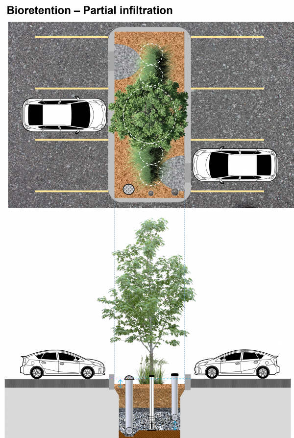
Bioretention refers to vegetated stormwater practices that temporarily store roof and pavement runoff in depressed planting beds or vertical-walled structures.
Depending on native soil infiltration rate and physical constraints, the facility may be designed without an underdrain for full infiltration, with an underdrain for partial infiltration, or with an impermeable liner and underdrain for no infiltration, "filtration only" (i.e., a stormwater planter or biofilter) design.
Bioretention can be adapted to fit into many different development contexts and provides a convenient area for snow storage and treatment.
This article is about full and partial infiltration design variations that capture and infiltrate some or all of the stormwater received.
For simple systems, without underdrains or storage reservoirs (typically found in residential settings), see Rain gardens.
For linear systems that have a gradually sloping filter media bed and can convey surface flow, but are otherwise similar to bioretention, see Bioswales.
For planted systems that are lined and do not infiltrate water, see Stormwater planters.
Overview[edit]
Bioretention systems may be the most well-recognized form of low impact development (LID). They can fit into any style of landscape and utilize all of the stormwater treatment mechanisms: sedimentation, infiltration, filtration, attenuation and evapotranspiration.
Bioretention is an ideal technology for:
- Fitting multi-functional vegetation into urban landscapes
- Treating runoff collected from nearby impervious surfaces
Take a look at the downloadable Bioretention Factsheet below for a .pdf overview of this LID Best Management Practice:

The fundamental components of a bioretention cell are:
- Inlets which may be curb openings (e.g. modified curbs, spillways), pipes, road or side inlet catchbasins, trench drains or other pre-fabricated inlet structures;
- A surface ponding area defined by landscaped side slopes or hardscape structures and the invert elevation of the overflow outlet structure;
- A filter bed containing filter media;
- A filter bed surface cover layer (e.g. mulch and stone);
- Plants, and;
- An overflow outlet to limit surface ponding and safely convey excess flow to a downstream storm sewer or the next BMP in the treatment train.
Additional components may include:
- An underdrain to redistribute or remove excess water and access structures or standpipes for periodic inspection and flushing;
- An internal water storage reservoir composed of a reservoir aggregate layer, and may include embedded void-forming structures to minimize depth and conserve aggregate, and organic material derived from untreated wood (aids in dissolved nitrogen removal);
- Monitoring wells installed to the base and screened in the underdrain aggregate to verify and track drainage time; and
- Filter media additives intended to enhance retention of nutrients, metals, petroleum hydrocarbons and/or bacteria.
- Impervious liner can be installed if the bioretention facility is designed as a stormwater planter and is in close proximity to buildings or in a tight space in an urbanized environment or if located near pollution hotspots/contaminated soils, or in areas with higher than normal water tables.
Planning considerations[edit]
Infiltration[edit]
Some form of stormwater landscaping (bioretention) can be integrated into most spaces. Although there are some constraints to infiltrating water, it is preferable to do so where possible. Designing bioretention without an underdrain is highly desirable wherever the soils permit infiltration at a rate which is great enough to empty the facility between storm events. Volume reduction is achieved primarily through infiltration to the underlying soils, with some evapotranspiration. As there is no outflow from this BMP under normal operating conditions, it is particularly useful in areas where nutrient management is a concern to the watershed.
Bioretention with an underdrain is a popular choice in areas with 'tighter' soils where infiltration rates are < 15 mm/hr. Including a perforated pipe in the reservoir aggregate layer helps to empty the facility between storm events, which is particularly useful in areas with low permeability soils. The drain discharges to a downstream point, which could be an underground infiltration trench or chamber facility. Volume reduction is gained through infiltration and evapotranspiration. By raising the outlet of the discharge pipe the bottom portion of the BMP can only drain through infiltration, creating an internal water storage reservoir. This creates a fluctuating anaerobic/aerobic environment which promotes denitrification. Increasing the period of storage has benefits for promoting infiltration, but also improves water quality for catchments impacted with nitrates. A complimentary technique is to include fresh wood mulch in the storage reservoir aggregate, which fosters denitrifying biological processes.
For more information about constraints to infiltration practices, and approaches and tools for identifying and designing within them see Infiltration.
Where infiltration is infeasible or not permitted, but the design calls for planted landscaping, try a stormwater planter instead.
Native Soil[edit]
Bioretention can be constructed over any soil type, but hydrologic soil group A and B are best for achieving water balance objectives. Facilities designed to infiltrate water should be located on portions of the site with the highest infiltration rates. For infiltration rates <15 mm/h an underdrain is recommended. Native soil infiltration rate at the proposed location and depth should be confirmed through in-situ measurements of hydraulic conductivity under field saturated conditions. See Design infiltration rate for further guidance.
Wellhead Protection[edit]
Facilities receiving road or parking lot runoff should not be located within the 2 year time-of-travel Wellhead Protection Area for municipal drinking water supply wells (refer to applicable drinking water source protection plan for details).
Available Space[edit]
- The principles of bioretention can be applied in any scenario where planting or vegetation would normally be found.
- In the conceptual design stage it is recommended to reserve approximately 10 to 20% of the contributing drainage area for the bioretention facility footprint.
- For optimal performance recommended ratios of impervious drainage area to pervious facility footprint area (I:P area ratio) range from 5:1 on low permeability soils (HSG C and D) to 20:1 on high permeability soils (HSG A and B).
- Minimum bioretention facility footprint area (i.e., filter bed area) is based on the design storm runoff volume and effective surface ponding depth.
- Bioretention cells work best when distributed, so that no one facility receives runoff from more than 0.8 Ha, although there is a trade-off to be considered regarding distributed collection and treatment versus ease of maintenance.
- Bioretention can be almost any shape, from having very curvilinear, soft edges with variable depth, to angular, hard-edged and uniform depth.
- Linear trench or swale geometries will drain faster than round or square shapes because they have larger perimeters.
- For ease of construction and to ensure that the vegetation has adequate space, cells should be no narrower than 0.6 m at any point.
- The maximum width of a facility is determined by the reach of the excavator, which should not be tracked into the cell.
Site Topography[edit]
Contributing slopes should be 1 to 5%. The filter bed surface should be flat to allow flow to spread out. A stepped, multi-cell design can also be used.
Available Head[edit]
If an underdrain is used, then an elevation difference of 1 to 1.5 m is needed between the inverts of the inlet and the downstream storm sewer.
Water Table[edit]
Maintaining a separation of 1 m between the elevations of the bottom of the practice and the seasonally high water table, or top of bedrock, is recommended. Lesser or greater values may be considered based on groundwater mounding analysis.
Pollution Hot Spot Runoff[edit]
To prevent groundwater contamination, runoff from pollution hot spots should not be treated by bioretention facilities designed for full or partial infiltration. No infiltration, "filtration only" facilities (with an impermeable liner) can be used.
Proximity to Underground Utilities[edit]
Designers should consult local utility design guidance for the horizontal and vertical clearances required between storm drains, ditches, and surface water bodies.
Karst[edit]
Infiltration designs are unsuitable in areas of known or implied karst topography and geologic formations.
Overhead Wires[edit]
Check to ensure whether the future tree canopy height in the bioretention area will interfere with existing overhead wires.
Setbacks From Buildings[edit]
If an impermeable liner is used, no setback is needed, although designing to maintain drainage away from the building is crucial. Where no liner is used, a setback of 4 m from the building foundations should be applied.
Context[edit]
In single family residential sites rain gardens most often take the form of a soft edged, traditional perennial planting bed. As many private industrial, commercial and institutional sites have landscaping around their parking lots, bioretention is an increasingly popular choice to manage stormwater in these contexts.
Streetscapes[edit]
Bioretention is a popular choice for making urban green space work harder. Design configurations include extending the cells to accommodate shade trees, and using retrofit opportunities to create complete streets with traffic calming and curb extensions or 'bump outs'. See Bioretention: Streetscapes
Parkland and Natural Areas[edit]
Naturalized landscaping and soft edges can make a bioretention facility 'disappear' into green space surroundings. In some scenarios, a larger bioretention (50 - 800 m2) cell may be used as an end-of-pipe facility treating both sheet flow and concentrated flow before it enters an adjacent water course. In these larger installations care must be made in the design to distribute the inflow, preventing erosion and maximizing infiltration.
For a table summarizing information on planning considerations and site constraints see Site considerations.
Design[edit]
| Poor design choice: Limits outflow water quality |
Better design choice: Improves outflow water quality |
|---|---|
| Single large cell design | Several smaller distributed or connected cells |
| Single concentrated inflow | Forebays or distributed flow |
| No pretreatment | Pretreatment provided as part of inlet design |
| Filter bed < 0.5 m | Filter bed > 0.75 m |
| Filter media Plant-Available Phosphorus > 40 ppm | Filter media Plant-Available Phosphorus < 40 ppm |
| Filter media is predominantly sand | Filter media is a mixture of sand, topsoil and organic material |
| Surface covered with turf grass and stone | Surface covered with mulch and dense, deeply rooting vegetation |
| Internal water storage reservoir not included in underdrain design | Internal water storage reservoir included in underdrain design |
Design Variations[edit]
The figures below illustrate three design variations for a parking lot bioretention cell that differ according to whether or not drainage via infiltration into underlying native soils is to be promoted (i.e., lined or unlined) and their outlet configuration (i.e., with or without an underdrain and location of the perforated pipe in the cross-section). Full infiltration design does not include an underdrain and is suitable on highly permeable soils (>15 mm/hr infiltration rate) and residential rain gardens. No infiltration or "filtration only" designs feature an impermeable liner and underdrain and are suitable on all soil types. Partial infiltration design, that includes an underdrain and internal water storage reservoir is recommended where native soil infiltration rate is less than 15 mm/hr and is the most common. All the figures are image map drawings from the following pages to compare side-by-side the differences between varying configurations.
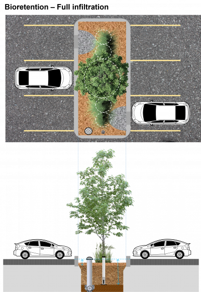
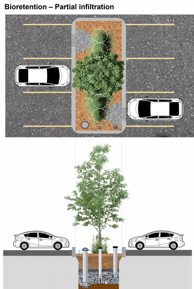
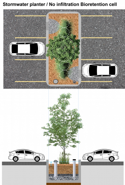
Sizing and Modelling[edit]
Bioretention facilities should be sized to accommodate runoff from approximately 5 to 20 times the footprint area of the facility. i.e. they should have an I/P ratio of 5 to 20. When the drainage area is too large, silt can accumulate very rapidly, overwhelm the pretreatment devices, and lead to clogging of the facility. When the drainage area is relatively small compared to the bioretention facility, it can make the facility unreasonably costly.
Inlets[edit]
- Bioretention may receive runoff via overland sheet flow from a pavement edge or flush curb, concentrated overland flow from a gutter, curb opening or spillway, or as concentrated underground flow from an inlet pipe.
- Distribute concentrated inflows between multiple inlets or facilities and include flow spreading features to dissipate energy and avoid erosion of the filter media bed.
- For concentrated overland flow from roads, inlets should be located at all sag points in the gutter grade and immediately upgrade of median breaks, crosswalks and street intersections. Inlet types include curb openings, side inlet catch basins, trench drains and pre-fabricated inlet structures. Spillways aid in turning flow 30, 45 or 90 degrees into the practice. Incorporate concrete aprons at curb opening or spillway locations to increase inflow effectiveness. Provide a 50 to 100 mm drop in elevation between inlet invert and mulch or concrete apron surface.
- For concentrated underground flow, inlets may include pipes from roof drains, catch basins, storm sewers, oil and grit separators (OGS) or outlet leader from an upstream best management practice.
See Inlets for further guidance.
Pretreatment[edit]
Pretreatment prevents clogging by capturing sediment before it reaches the filter bed. It is typically necessary unless runoff sediment loads are very low (e.g. roof drainage). Pretreatment options include:
- Level spreader: A shallow trench structure (with concrete, metal or wood lip), graded to be level and installed parallel to the pavement edge or flush curb. Recommended sizing: (i) 1.4 m of length for every 0.01 m³/s of inflow during the design storm event, (ii) width of 300 mm or 3 times inflow pipe diameter, (iii) depth of 200 mm or half the inflow pipe diameter. Used with any overland flow inlets.
- Gravel diaphragm: A shallow, geotextile-lined depression, filled with clean aggregate, graded level and installed parallel to pavement edge (for sheet inflows) or perpendicular to concentrated inflows. Elevation change of 75 to 100 mm from pavement to top of diaphragm. Typically 600 mm wide by 300 mm deep. Stone: 5 to 20 mm (sheet flow inlets) or rip rap for concentrated inflows. Used with overland flow inlets.
- Vegetated filter strip: Receive runoff as overland sheet flow via pavement edge or flush curb. Use where drainage area flow path length is ≤ 25 m and slopes are <3%. Min. flow path length of 3 m, with 5 m preferred, and slope between 1 and 3%. Must be graded to provide a 75 to 150 mm elevation drop between the pavement and the filter strip surface.
- Catch basin, manhole, or other inlet structure sump: Consider using shield, baffle, trap or filter insert device to increase removal of sediment and debris. Used with overland or underground concentrated inflows.
- Forebay: Constructed with 2:1 length to width ratio and sized to accommodate ponding volume of 25% of the surface ponding storage requirement. Used with concentrated overland flow inlets.
- Oil and grit (hydrodynamic) separator. Used with concentrated underground flow inlets (inlet pipes).
See Pretreatment for further guidance.
Overflow Configuration[edit]
Bioretention can be designed to be inline (accepts all flow from the drainage area and conveys large event flows through an overflow outlet) or offline (allows only the design storm runoff storage volume to enter the facility). Overflow structures must be sized to safely convey large event flows out of the facility.

Routing[edit]
- Infiltration facilities can be designed to be inline or offline from the drainage system. See figure to the right for an illustration.
- Inline facilities accept all of the flow from a drainage area and convey larger event flows through an overflow outlet. The overflow must be sized to safely convey larger storm events out of the facility. The overflow must be situated at the maximum surface ponding elevation or furthest downgradient end of the facility to limit surface ponding during periods of flow in excess of the facility storage capacity.
- Offline facilities use flow splitters or bypass channels that only allow the design storm runoff storage volume to enter the facility. Higher flows are conveyed to a downstream storm sewer or other BMP by a flow splitting manhole weir or pipe, or when the maximum surface ponding depth has been reached, by by-passing the curb opening and flowing into a downstream catchbasin connected to a storm sewer.
Overflow Elevation[edit]
The invert of the overflow should be placed at the maximum water surface elevation of the practice (i.e. the maximum surface ponding level). A good starting point is 150 to 350 mm above the surface of the mulch cover. However, consideration should be given to public safety, whether or not an underdrain is included, the time required for ponded water to drain through the filter bed surface, and if no underdrain is present, into the underlying native soil (must drain within 48 hours). See Bioretention: Sizing and Stormwater planters for more details.
Freeboard[edit]
- In swales conveying flowing water a freeboard of 300 mm is generally accepted as a good starting point.
- In bioretention the freeboard is the difference between the invert elevation of the inlet and overflow structure. 150 mm will usually suffice, so long as the inlet will not become inundated during design storm conditions.
- In above grade stormwater planters, the equivalent dimension would be the difference between the invert elevation of the lip of the planter and the overflow structure (150 mm minimum).
Overflow Outlet Options[edit]
Metal grates are recommended (over plastic) in all situations.
| Feature | Anti Vandalism/Robust | Lower Cost Option | Self cleaning |
|---|---|---|---|
| Dome grate | x | ||
| Flat grate | x | ||
| Catch basin | x | ||
| Ditch inlet catch basin | x | x | |
| Curb cut | x | x | x |
Gallery[edit]
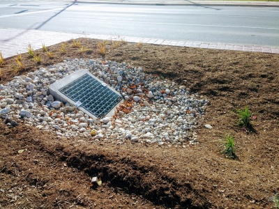
Flat metal overflow with stone surround to reduce erosion around the cast concrete structure. Mississauga Road, ON
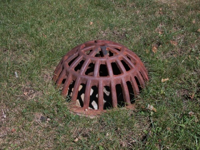
Domed, metal overflow grate. Being flush with the surface reduces potential infiltration of ponded water. Photo credit: Aaron Volkening
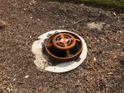
Overflow inlet for newly constructed stormwater bioretention areas in median of Bradley Road. Village of Brown Deer, Wisconsin. Bradley Road, east of 51st Street. Photo from October 2015. Constructed summer 2015.
Photo credit: Aaron Volkening
Flat, metal overflow grate in Emeryville California Stormwater Curb Extension
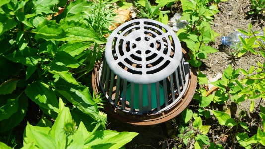
Note the greyish colour change indicating UV degradation of this plastic overflow inlet in a bioretention cell; metal is recommended instead. Mississauga ON.


Filter Media Bed[edit]
Recommended filter media bed depth is 0.5 to 1.0 m, but in constrained applications pollutant removal benefits may be achieved by beds as shallow as 0.3 m. Plant-specific depths recommended are 0.3 m to support grasses and perennials, 0.6 m to support shrubs and 1.0 metre to support trees. Filter bed must be installed level, with maximum side slopes of 1:3 or 33%. Maintaining a 75 to 100 mm layer of double shredded wood mulch is recommended on portions of the filter bed surface not covered by plantings. Benefits include soil moisture preservation, suppression of weed growth and enhanced water treatment. Erosion-prone inlets may require stone instead of mulch. Filter media should come pre-mixed from an approved vendor, be free of stones or debris greater than 50 mm diameter.
- Blend A - Use when drainage rate is the priority (when I:P ratio ≥15:1). Consists of 3 parts sand to 1 part organic material/additives.
- Blend B – Use when water quality treatment (phosphorus, metals) is the priority and more diverse planting options are desired. Consists of 3 parts sand to 2 parts topsoil to 1 part organic material/additives.
See Filter media for detailed guidance on different blends, required performance criteria, and specifications and laboratory tests for blend components and the filter media itself.
Geotextiles[edit]
To avoid clogging, the use of geotextile on the bottom of bioretention facilities or between filter media and underdrain aggregate materials should be avoided. Including a choker layer of clear stone aggregate to maintain separation between filter media and underlying aggregate is recommended instead. Geotextile socks should be installed on underdrain pipes with 360 degree perforations. Alternatively a strip of geotextile may be placed over the pipe to limit migration of fines from the overlying filter media into the pipe. Geotextile may be installed on the sides of the bioretention cell to maintain separation between backfill materials during construction. Geotextile used for weed control (i.e. landscape fabric) within the filter media bed or under mulch should be avoided. Geotextile that is used should have material specifications that conform to Ontario Provincial Standard Specification (OPSS) 1860 for Class II geotextile fabrics. Should be woven monofilament or non-woven needle punched fabrics. See Geotextiles for further guidance.
Underdrain[edit]
- Recommended where native soil infiltration rate is less than 15 mm/h (hydraulic conductivity < 1x10⁻⁶ cm/s) and needed for non-infiltrating, filtration only designs.
- Typically comprised of a length of perforated pipe embedded near the top of the storage reservoir, with an overlying choker layer of medium-sized aggregate, and structures to provide inspection and maintenance access.
- Alternatively the perforated pipe could be installed on the reservoir bottom and connected to an upturned pipe assembly or riser.
- May include an optional flow restrictor (e.g., orifice cap or valve) on the underdrain outlet pipe or outlet storm sewer, to provide erosion control and optimize infiltration while meeting the required drainage time.
- Continuously perforated, smooth interior HDPE or PVC pipe with diameter ≥ 200 mm to reduce freezing risk and facilitate access by camera and cleaning equip. Solid pipe leaders from inlet structures should extend 300 mm into the storage reservoir before transitioning to perforated pipe. Transitions back to solid pipe to connect to outlet storm drain system.
- See Underdrains for further guidance.
Choker Layer[edit]
A minimum 100 mm deep layer of clean 5 to 20 mm diameter angular or rounded stone (e.g. High Performance Bedding, HL-6, pea gravel) should be placed on top of the coarser storage reservoir aggregate to prevent downward migration of filter media into the reservoir and pipe. See Aggregates for further details.
Storage Reservoir[edit]
Should be a minimum of 300 mm deep, and filled with granular material of washed 25 or 50 mm diameter crushed angular stone (max. wash loss of 0.5%). See Aggregates for further details. Include organic material derived from untreated wood (e.g. chips, mulch or shavings) to enhance nitrogen removal. Also see Bioretention: Internal water storage. See Bioretention: Sizing for reservoir sizing guidance, including depth and area of surface ponding and reservoir volume needed to capture and store the design storm.
Monitoring wells and perforated pipe access structures[edit]
- Monitoring well should be a vertical standpipe consisting of an anchored 100 to 150 mm diameter pipe with perforations along the length within the reservoir, installed to the bottom of the facility, with a lockable cap. The well allows monitoring of post-event drainage times. See Monitoring wells for further guidance.
- Access structures, used for inspection and maintenance of the underdrain perforated pipes may be a maintenance hole or vertical standpipe connected to the pipe. Couplings used for standpipe connections should be 45° to facilitate pipe access by push camera or cleaning equipment. See Underdrains for further guidance.
Plants[edit]
Plantings on the filter bed should be dense to help maintain surface infiltration and improve sediment settling and retention of dissolved contaminants. It is recommended that perennial forbs and grasses are planted 0.5 m on center, and no more than 0.6 m on center. Planting plans should feature a mixture of deeply rooting perennials adapted to both wet and dry conditions and local climate. Road salt tolerance should be considered if facility will receive pavement runoff. Native plants are often the most hearty, adaptable, salt tolerant and deeply rooted options for bioretention planting. Invasive plants should not be planted in bioretention areas.
Plant Selection[edit]
The nature of bioretention cells is to attenuate stormwater from rainfall events of varying intensities. For this reason, the vegetation used must be suitable for the varying moisture conditions and is often categorized into three zones related to the grading of the feature.

- Low Zone -- This area is frequently inundated during storm events, and is well-drained between rainfall events.
- Mineral Meadow Marsh plant community.
- Grasses, sedges, rushes, wildflowers, ferns and shrubs that have an ‘obligate’ to ‘facultative’ designation.
- Wetland 'obligate' species that are flood tolerant as they will persist in average years and flourish in wetter years.
- Plants that are likely to occur in wetlands or adjacent to wetlands.
- Plants with dense root structure and /or vegetative cover are favoured for their ability to act as pollution filters and tendency to slow water velocity.
- Be advised these practices are not constructed wetlands and are designed to fully drain within 48 hours.
- Mid Zone -- This zone is inundated less frequently (2 – 100 year storm events) and has periodically high levels of moisture in the soil. The ecology of this zone is a transition from the Mineral Meadow Marsh/Beach-type community to an upland community.
- Plants able to survive in soils that are seasonally saturated, yet can also tolerate periodic drought.
- Species include grasses and groundcovers, as well as low shrub species.
- High Zone -- The ecology of this zone is terrestrial due to its elevation in relation to the filter bed. The zone most closely resembles a Cultural Meadow or a Cultural Thicket community, depending on the mix of grasses, herbaceous material, shrubs and trees utilized.
- Plants should have deep roots for structure, be drought-tolerant and capable of withstanding occasional soil saturation.
- Trees and large shrubs planted in this zone will aid in the infiltration and absorption of stormwater.
- This area can be considered a transition area into other landscape or site areas.
- A variety (min. five) species should be used to avoid monocultures.
Exposure to roadway or parking lot runoff must be considered.
- Exposure to roadway or parking lot runoff
- Select salt tolerant grasses, other herbaceous material and shrubs.
- These can take on several forms, including parking lot islands, traffic islands, roundabouts, or cul-de-sacs and are often used as snow storage locations.
- No exposure to roadway or parking lot runoff
- Practices allow for a greater range of species selection.
- These receive runoff from rooftops or areas that use no deicing salt and have low pollutant exposure, such as courtyard bioretention.
Other selection factors:
- Most bioretention cells will be situated to receive full sun exposure. The ‘Exposure’ column in the plant lists identifies the sun exposure condition for each species.
- Facilities with a deeper filter media bed (e.g., 1 m) provide the opportunity for a wider range of plant species (including trees).
- The inclusion of vegetation with a variety of moisture tolerances ensures that the bioretention cell will adapt to a variety of weather conditions.
- Proper spacing must be provided for above-ground and below-ground utilities, and adjacent infrastructure.
- Where possible, a combination of native trees, shrubs, and perennial herbaceous materials should be used.
- A planting mix with evergreen and woody plants will provide appealing textures and colors year round, but are not appropriate for areas where snow will be stored/piled during winter.
- In areas where less maintenance will be provided and where trash accumulation in shrubbery or herbaceous plants is a concern, consider a “turf and trees” landscaping model.
- If trees are to be used, or the bioretention is located in a shaded location, then ensure that the chosen herbaceous plants are shade tolerant.
- Spaces for herbaceous flowering plants can be included. This may be attractive at a community entrance location or in a residential rain garden.
Tables for identifying ideal species for bioretention are found in the Plant lists. See plant selection and planting design for supporting advice.
Construction[edit]
Where possible, bioretention areas should be kept offline until construction is complete, the drainage area stabilized, and vehicle mud tracking has stopped. Diverting flows around the facility offers several benefits, including:
- less risk of erosion, clogging, and compaction;
- greater opportunity for establishment of seeded/planted areas; and
- easier access for construction, repairs or maintenance of the area.
Where diverting flows around the facility is not possible, and its location requires that it be used as a temporary runoff detention basin, protection measures can prevent fine sediment from migrating into the subgrade. During construction, the area should only be excavated to 75 cm above the final post-construction base of the facility. This layer of native soil will retain fine particles so that they will not migrate down into the subsoils. To prevent compaction during bioretention construction, heavy equipment should not enter the footprint of the bioretention area. For more detailed guidance, see the LID Construction Guide [2] and the Erosion and Sediment Control Guide for Urban Construction [3].
Take a look at the Construction and Finishing grades and surface layer installation: vegetated LIDs pages by clicking below for further details about proper construction practices:
Inspection and Maintenance[edit]
Bioretention requires regular, routine inspection and maintenance of the landscaping as well as periodic inspection of other parts of the facility. Routine maintenance should include weeding, pruning, and mulching, similar to other landscaped areas, as well as the removal of trash, debris and sediment accumulated in pretreatment areas, inlets and outlets. Watering may be needed until plant establishment (first 2 years). Periodic replacement of the top 5 cm of filter media around inlets (e.g., every 5 to 10 years) will help maintain treatment performance.
Inspections should occur twice annually (spring and late fall) and after major storm events. Inspect for vegetation density (≥ 80% coverage), damage by foot or vehicle traffic, erosion, debris and sediment accumulation, and damage to pretreatment devices.
Cleanouts and access points should be provided to allow clean-out of the underdrain and overflow pipe. Camera inspection of these pipes should be conducted every 5 years to ensure pipes are free of roots, sediment and debris. Hydraulic flushing or root removal may be needed to clear debris or obstructions.
Take a look at the Inspection and Maintenance: Bioretention & Bioswales page by clicking below for further details about proper inspection and maintenance practices:

Life Cycle Costs[edit]
To learn about life cycle costs associated with this practice (i.e. Pre-construction, Excavation, Materials & Installation, Project Management, Overhead, Inspection and Maintenance, Rehabilitation and other associated costs), visit the Bioretention: Life Cycle Costs page to view accurate (found to be within ±14% of actual construction costs[4]) BMP cost estimates for full-, partial- and no-infiltration design variations. Alternatively you can use the STEP's Low Impact Development Life Cycle Costing Tool (LID LCCT) to generate cost estimates customized to your own LID stormwater design project specifications.
Take a look at the Bioretention: Life Cycle Costs page by clicking below for further details:

Performance[edit]
| BMP | Water Balance | Water Quality | Erosion Control |
|---|---|---|---|
| Bioretention with no underdrain | Yes | Yes-size for water quality storage requirement | Partial-based on available storage volume and native soil infiltration rate |
| Bioretention with underdrain | Partial-based on available storage, native soil infiltration rate and if a flow restrictor is used | Yes-size for water quality storage requirement | Partial-based on available storage, native soil infiltration rate and if a flow restrictor is used |
| Bioretention with underdrain and liner | No-some volume reduction occurs through evapotranspiration | Yes-size for water quality storage requirement | Partial-some volume reduction occurs through evapotranspiration |
Water Balance[edit]
Bioretention practices have been shown to reduce runoff volume through both means of evapotranspiration and infiltration. The primary body of research is separated into bioretention practices either with underdrains and those without (therefore, relying solely on full infiltration into underlying soils). Volumetric performance improves when:
- Native soils have high infiltration capacity and facility is designed for full infiltration, without an underdrain;
- Size of the impervious drainage area relative to the facility permeable footprint area (i.e., I:P area ratio) is kept within recommended range of 5:1 (HSG C and D soils) to 20:1 (HSG A and B soils).
- Perforated pipe or outlet connection is elevated above the bottom of the practice in the underdrain cross-section;
- A flow restrictor (e.g., orifice, valve) is installed on the underdrain or storm sewer outlet pipe.
| LID Practice | Location | Runoff Reduction* | Reference |
|---|---|---|---|
| Bioretention without underdrain | China | 85 to 100%* | Gao, et al. (2018)[5] |
| Connecticut | 99% | Dietz and Clausen (2005) [6] | |
| Pennsylvania | 80% | Ermilio (2005)[7] | |
| Pennsylvania | 70% | Emerson and Traver (2004)[8] | |
| Bioretention with underdrain | |||
| Ontario | 64% | CVC (2020)[9] | |
| Ontario | 66% | STEP (2019)[10] | |
| Texas | 82%* | Mahmoud, et al. (2019)[11] | |
| China | 35 to 75%* | Gao, et al. (2018)[12] | |
| Ohio | 36 to 59% | Winston et al. (2016)[13] | |
| Ontario | 90% | STEP (2015)[14] | |
| Ontario | 91 to 96% | TRCA (2014)[15] | |
| Virginia | 97 to 99% | DeBusk and Wynn (2011)[16] | |
| Maryland and North Carolina | 20 to 50% | Li et al. (2009) [17] | |
| North Carolina | 40 to 60% | Smith and Hunt (2007)[18] | |
| North Carolina | 33 to 50% | Hunt and Lord (2006) [19] | |
| Bioretention with underdrain & liner | |||
| Ontario | 15 to 34% | STEP (2019) [20] | |
| Queensland, Australia | 33 to 84% | Lucke and Nichols (2015) [21] | |
| Victoria, Australia | 15 to 83% | Hatt et al. (2009)[22] | |
| Maryland | 49 to 58% | Davis (2008)[23] | |
| Runoff Reduction Estimate* | 85% without underdrain;
45% with underdrain | 30% with underdrain and liner | ||
Water Quality[edit]
Performance results from both laboratory and field studies indicate that bioretention systems have the potential to be one of the most effective BMPs for pollutant removal (TRCA, 2009). Bioretention provides effective removal for many pollutants as a result of sedimentation, filtering, soil adsorption, microbial processes and plant uptake. It is also important to note that there is a relationship between the water balance and water quality functions. If a bioretention cell infiltrates and evaporates 85 to 100% of the runoff from the drainage area during the design storm event, then there is little to no pollution leaving the site in surface runoff. Furthermore, treatment of infiltrated runoff continues to occur as it moves through the native soil.
A comparative performance assessment of bioretention in Ontario was conducted comparing 9 different bioretention facilities in the GTA. The results showed total suspended solids (TSS) load reductions between 88 to 99%, and total phosphorus load reductions between 68 and 92% for unlined facilities. Results for a lined bioretention swale for TSS and Total Phosphorus load reduction were 73 to 79% and -18 to -21% respectively.(STEP, 2019)[24]. Negative TP load reduction values were observed because effluent concentrations were higher than influent concentrations, and volume reduction through evapotranspiration was not sufficient to offset the increase in phosphorus concentration in biofilter effluent. (STEP, 2018)[25]. Other STEP studies in the Greater Toronto Area have displayed similar results, with 90% reduction in TSS load when compared to nearby asphalt runoff samples having median TSS concentrations near the provincial 30 mg/L standard (median = ~19 mg/L) STEP, 2014 [26].
Another group of studies of bioretention facilities examines nutrient removal of these LID installation, with mixed results. Some facilities have been observed to increase total phosphorus in infiltrated water (Dietz and Clausen, 2005[27]; Hunt and Lord, 2006[28] ; TRCA, 2008[29]). These findings have been attributed to leaching from filter media soil mixtures which contained high phosphorus content. To avoid phosphorus export, the plant-available (extractable) phosphorus content of the filter media soil mixture should be examined prior to installation and kept between 12 to 40 ppm (see Filter media; Hunt and Lord, 2006). A design option to increase phosphorus removal performance of bioretention is to incorporate additives into the filter media bed, either blended into the media or as a layer in the aerobic portion of the filter bed, such as iron filings (i.e., zero valent iron)[30], fly ash[31] [32], iron (ferric) or aluminum hydroxide-based water treatment residuals (by-product from drinking water treatment)[33] [34], biochar [35] [36], proprietary filter media additives or blends, or by using iron-rich sand in the filter media blend. Read about a field evaluation comparing the phosphorus retention performance of parking lot bioretention cells featuring iron-rich sand and proprietary reactive media additive (Sorptive PTM) in the STEP technical brief[37]. While moderate reductions in total nitrogen and ammonia nitrogen have been observed in laboratory studies (Davis et al., 2001[38]) and field studies (Dietz and Clausen, 2005[39]), nitrate nitrogen removal has consistently been observed to be low. Design innovations to enhance nitrate-nitrogen removal performance of bioretention is an area of active research. Promising results have been observed from laboratory column and field-scale evaluations of underdrained practices featuring internal water storage reservoirs containing mixtures of clear stone aggregate and shredded newspaper or wood chips, which creates low oxygen or anoxic conditions and promotes conversion of nitrate-nitrogen to nitrogen gas via denitrification [40] [41] [42].
Roseen et al. (2013) conducted both field and laboratory testing on the performance of bioretention cells featuring filter media amended with drinking water treatment residuals (WTR) with low solids content (5-10% solids) as an additive. Water treatment residuals were included at 10-15% of the total filter media mix by volume. Amended bioretention cells had median orthophosphate removal efficiencies of 90-99%. A second study found a bioretention design featuring WTR amended filter media and an internal water storage zone optimized to remove phosphorus and nitrogen had an orthophosphate removal efficiency of 20% and effluent concentrations below 0.02 mg/L.[43] More recently, LeFevre et al. (2015) present a state-of-the-art review of dissolved stormwater pollutant sources (focusing on nutrients, toxic metals and organic compounds), typical concentrations, and removal mechanisms and fate in bioretention, along with design options to enhance their retention [44].

The two box plot figures to the right show combined stormwater effluent quality results from STEP monitoring projects conducted over a 16-year time period (between 2005 and 2021) at sites within Greater Toronto Area (GTA) municipalities. Total Suspended Solid (TSS) effluent concentration results for bioretention practices represent the combined results from 9 sites in the GTA. Median TSS concentration was found to be 9.5 mg/L and exceeded the Canadian Water Quality Guideline of 30 mg/L (CCME, 2002[45]) during only 15% of the 301 monitored storm events, similar to STEP Permeable Pavements performance results. In comparison, median TSS effluent concentration for bioretention in the International Stormwater BMP Database was found to be 10.0 mg/L, based on 685 monitored storm events (Clary et al. 2020)[46], so quite similar to results from STEP studies. Median TP concentration was found to be 0.09 mg/L and exceeded the Ontario Provincial Water Quality Objective (PWQO) of 0.03 mg/L (OMOEE, 1994[47]) during 86% of the 355 monitored storm events. In comparison, median TP effluent concentration for bioretention in the International Stormwater BMP Database was found to be 0.240 mg/L, based on 667 monitored storm events (Clary et al. 2020)[48], which is well above the Ontario PWQO of 0.03 mg/L. These results indicate that the design of bioretention draining to phosphorus-limited receiving waterbodies should include variations to improve Phosphorus retention. An example of such a design variation is including sorption additives in Bioretention: Filter media. Please refer to the Phosphorus and Additives pages for further guidance. Another example of a design variation to enhance retention of phosphorus is including a sorption media filter manufactured treatment device as part of the treatment train design.

The mechanisms involved in, and ability of bioretention to reduce bacteria and other microbial pathogen concentrations is also an area of active research. Preliminary laboratory and field study results report good but variable removal rates for fecal coliform bacteria from biofilters and bioretention cells (Rusciano and Obropta, 2005[49]; Hunt et al., 2006[50]; TRCA, 2008[51]). In a recent review, Clary et al. (2020) report bioretention E.coli removal efficiency of 42.5% and fecal coliform removal efficiency of 99.4% based on median inlet and outlet concentrations from 12 and 8 studies, respectively [52]. In a recent article, Peng et al. (2016) review factors influencing microbial removal and effects of design choices on treatment performance. They found that approaches for improving the removal of microorganisms by biofilters could involve altering the grain size range and surface properties of the filter media. This could involve the use of filter media with smaller average grain sizes, the inclusion of additives (e.g., activated carbon, zeolite, or biochar) to improve filtration rates, or chemical modifications of filter media grain surfaces (e.g., with biocides) to promote microbial die-off. Including an internal water storage reservoir was also found to improve microbial removal rates [53].
Recent research into the role of plants in bioretention confirms they play an important roles in hydraulic and nitrogen removal performance. In a recent review of scientific literature, Dagenais et al. (2018) found that planted facilities are more effective than unplanted ones, as the presence of plants increases filter bed permeability and nitrogen removal. Plant species selection can considerably affect hydraulic and nitrogen removal performance, with root traits (e.g., thickness and depth) identified as playing important roles. They identified further research needed to test the hypothesis that native or diversely-planted facilities perform better than ones planted with exotic or fewer species.[54]
Stream Channel Erosion[edit]
The feasibility of storing the channel erosion control volume within bioretention areas will be dependent on the size of the drainage area and available space. Meeting the channel erosion control requirement through bioretention is most feasible in the regions of the Greater Toronto Area with Hydrologic Soil Group A and B soils. In these situations, the reduction in runoff volume through infiltration and evapotranspiration may be sufficient. For facilities with constrained footprints, include a flow restrictor on the underdrain perforated pipe or outlet storm sewer to control the release rate, and size the internal water storage reservoir to retain the necessary volume of water. Where acceptable, consider increasing the maximum ponding depth beyond the recommended 350 mm. It is important to note that the bioretention practice will infiltrate runoff into the filter media bed and underlying native soil over the duration of the design storm event, which can be factored into surface ponding and internal water storage reservoir sizing to optimize the design. See Sizing for further guidance.
Other Benefits[edit]
The benefits of bioretention reach beyond the specific stormwater management goals to other social and environmental benefits, including:
- Reduced thermal aquatic impacts: Bioretention and other filtration and infiltration practices benefit aquatic life by reducing thermal impacts on receiving waters from urban runoff (Jones and Hunt, 2009[55]). Unlike detention ponds, bioretention does not raise water temperature and can help maintain baseflows through infiltration.
- Snow Storage: Bioretention areas can be used for snow storage and snow melt treatment from the contributing drainage area during winter, especially those located adjacent to parking lots and roadways. To function as snow storage, bioretention must include an overflow for snow melt in excess of the designed ponding depth. Additionally, the plant material must be salt-tolerant, perennial and tolerant of periodic inundation.
- Reduced Urban Heat Island: Bioretention is able to reduce the local urban heat island by introducing soils and vegetation into urban areas, such as parking lots. Vegetation absorbs less solar radiation than hard urban surfaces. Also, the water vapor emitted by plant material also cools ambient temperatures.
See also[edit]
External links[edit]
- City of Toronto Green Streets Technical Guidelines - Version 1.0 (2017) Schollen & Company Inc., Urban Forest Innovators, TMIG, DMG
- CSA W200-18 Design of Bioretention Systems (2018) CSA Group
- CSA W201-18 Construction of Bioretention Systems (2018) CSA Group
- Bioretention Design Guidelines (2014) Healthy Waterways (Australia)
Gallery[edit]
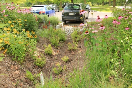
Parking lot bioretention with surface ponding well in foreground, Kortright Centre, Vaughan, ON. Read about the performance of this practice in the technical brief.
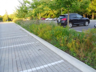
Parking lot bioretention sharing underground reservoir with adjacent permeable paving, Edwards Gardens, Toronto, ON. Read a case study about it here.
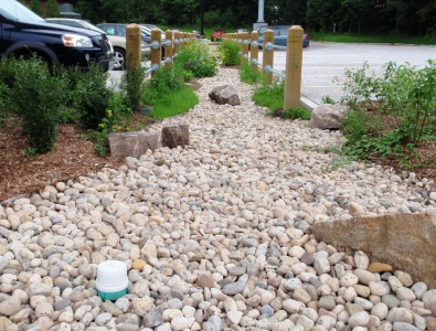
Parking lot bioretention with decorative stone for erosion control, and perforated pipe access standpipe in foreground, Earth Rangers Centre, Vaughan, ON. Read about the performance of this practice in the technical brief.

The sunken curb holds the edge of the asphalt pavement and lets water freely flow to the bioretention cell beside the 7sigma parking lot in Minneapolis, MN (USA)
Photo credit:Brian Ash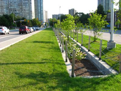
Bioretention cells on Elm Drive, Mississauga, ON, with vertical sides and hardscape perimeter receive road runoff via leader pipes from road catch basin inlets. Read about the stormwater system at this site in the performance assessment report.
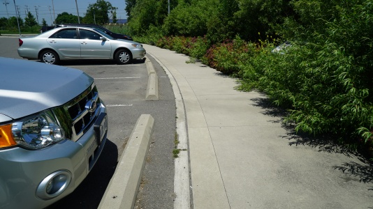
The grade and lack of curb allow for sheet-flow runoff into this bioretention facility. Lakeside Park, Mississauga, ON
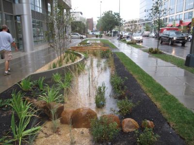
Bioretention cell receiving road and walkway runoff in a high density development setting.
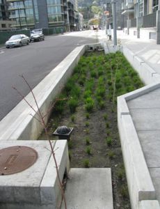
Bioretention bump out in a dense urban setting receiving runoff via side inlet catch basin and curb openings on the walkway side of the installation.
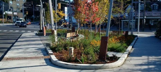
Fairford Parkette featuring a bioretention cell retrofitted into a roadway in downtown Toronto, ON. Read a case study about it here.
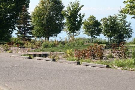
Bioretention cell located in Waterfront Park in Ajax, ON.
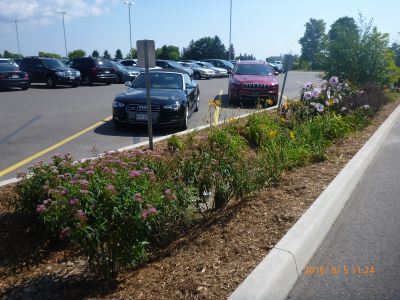
Parking lot bioretention cell at IMAX corporate headquarters in Mississauga, ON. Read about the IMAX stormwater system in the performance assessment report
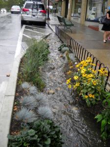
A curb extension bioretention cell in action during a major rain event.
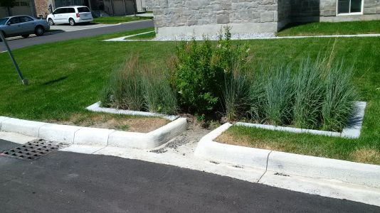
Bioretention cell receiving road runoff in the Wychwood neighbourhood of Brampton, ON. The nearby catch basin conveys overflows during major rain events. Read about the stormwater system in this community in the performance assessment report.
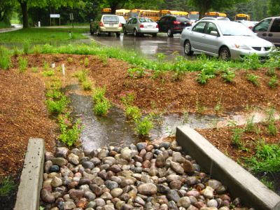
Kortright Centre parking lot bioretention cell in action during a rain event, Vaughan, ON.


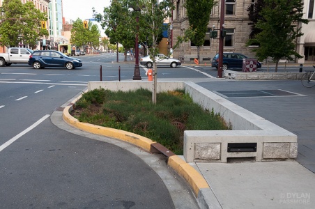
Curb extension in Victoria. Image credit Dylan Passmore
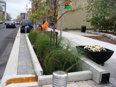
'Offline' streetscape bioretention with trees, King Street, Kitchener
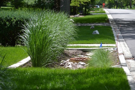
Bioretention on residential street, with covered drain inlet (grate in the gutter) and iron grate covered overflow in the centre of the cell, Hinsdale, IL Photo credit: CNT
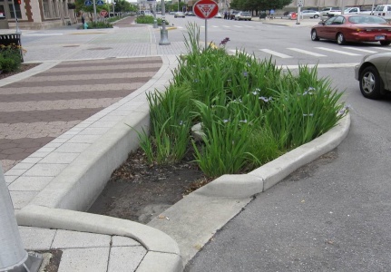
Curb extension in downtown Indianapolis, IN
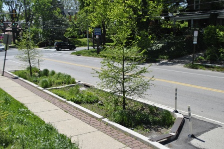
Curb extension on Queen Lane, in Philidelphia
Photo credit: PWD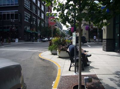
Curb extension with Urban Tree in a tree grate, in city showcased by the U.S Department of Transportation's, Federal Highway Administration.
Photo credit: Jennifer Rosales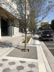
Boulevard with Urban Trees along the boulevard in tree grates, in Orlando, FL.
Photo credit: Design by: GAI Consultants/Kevin Aust & Contractor: UCC Group.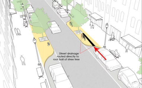
Schematic of Urban Trees in tree grates in a proposed traffic-calming bump-out as part of the on Columbus Av. New York City, NY. The red arrow depicts the flow of water to the stormwater tree trench system.
Photo credit: Jonathan Toner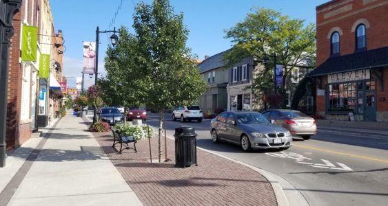
Curb extension with planted tree in open tree pit, part of a finished soil cell system - a tree grate for safety reasons and increased aesthetic should be added. Located on Main St. Markham, ON.
Photo credit: GreenBlue Urban Inc.


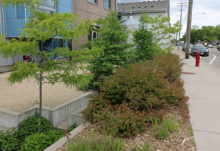
Rainwater harvesting cistern, which discharges to tree pits during dry conditions. Image credit Mississippi WMO

Extended tree pit planting in USA
Photo credit: USEPA
A right of way bioswale installed by the New York City Department of Environmental Protection on Dean Street, Brooklyn

.jpg)

References[edit]
- ↑ CVC. 2022. Native Plants for Rain-ready Landscapes> plant these native wildflowers, grasses, shrubs and groundcovers to help manage stormwater - beautifully. cvc.ca/GreenYourProperty. https://cvc.ca/wp-content/uploads/2022/03/com_lo_rain-ready-guide_20220328-FINAL3.pdf
- ↑ Credit Valley Conservation. 2012. LID Construction Guide. https://cvc.ca/wp-content/uploads/2012/01/CVC-LID-Construction-Guide-Book.pdf
- ↑ Toronto and Region Conservation Authority. 2019. Erosion and Sediment Control Guide for Urban Construction. https://sustainabletechnologies.ca/app/uploads/2020/01/ESC-Guide-for-Urban-Construction_FINAL.pdf
- ↑ Credit Vally Conservation (CVC). 2019. Life-cycle costing tool 2019 update: sensitivity analysis. Credit Valley Conservation, Mississauga, Ontario. https://sustainabletechnologies.ca/app/uploads/2020/04/LCCT-Sensitivity-Analysis_March2020.pdf
- ↑ Gao, J., Pan, J., Hu, N. and Xie, C., 2018. Hydrologic performance of bioretention in an expressway service area. Water Science and Technology, 77(7), pp.1829-1837.
- ↑ Dietz, M.E. and J.C. Clausen. 2005. A field evaluation of rain garden flow and pollutant treatment. Water Air and Soil Pollution. Vol. 167. No. 2. pp. 201-208. http://citeseerx.ist.psu.edu/viewdoc/download?doi=10.1.1.365.9417&rep=rep1&type=pdf
- ↑ Ermilio, J.F., 2005. Characterization study of a bio-infiltration stormwater BMP (Doctoral dissertation, Villanova University). https://www1.villanova.edu/content/dam/villanova/engineering/vcase/vusp/Ermilio-Thesis06.pdf
- ↑ Emerson, C., Traver, R. 2004. The Villanova Bio-infiltration Traffic Island: Project Overview. Proceedings of 2004 World Water and Environmental Resources Congress (EWRI/ASCE). Salt Lake City, Utah, June 22 – July 1, 2004. https://ascelibrary.org/doi/book/10.1061/9780784407370
- ↑ Credit Valley Conservation. 2020. IMAX Low Impact Development Feature Performance Assessment. https://sustainabletechnologies.ca/app/uploads/2022/03/rpt_IMAXreport_f_20220222.pdf
- ↑ Sustainable Technologies Evaluation Program. 2019. Improving nutrient retention in bioretention. https://sustainabletechnologies.ca/app/uploads/2019/06/improving-nutrient-retention-in-bioretention-tech-brief.pdf
- ↑ Mahmoud, A., Alam, T., Rahman, M.Y.A., Sanchez, A., Guerrero, J. and Jones, K.D. 2019. Evaluation of field-scale stormwater bioretention structure flow and pollutant load reductions in a semi-arid coastal climate. Ecological Engineering, 142, p.100007. https://www.sciencedirect.com/science/article/pii/S2590290319300070
- ↑ Gao, J., Pan, J., Hu, N. and Xie, C., 2018. Hydrologic performance of bioretention in an expressway service area. Water Science and Technology, 77(7), pp.1829-1837.
- ↑ Winston, R.J., Dorsey, J.D. and Hunt, W.F. 2016. Quantifying volume reduction and peak flow mitigation for three bioretention cells in clay soils in northeast Ohio. Science of the Total Environment, 553, pp.83-95.
- ↑ Sustainable Technologies Evaluation Program. 2015. Performance Comparison of Surface and Underground Stormwater Infiltration Practices. https://sustainabletechnologies.ca/app/uploads/2016/08/BioVSTrench_TechBrief__July2015.pdf
- ↑ Toronto and Region Conservation Authority. 2014. Performance Evaluation of a Bioretention System - Earth Rangers, Vaughan. Sustainable Technologies Evaluation Program. https://sustainabletechnologies.ca/app/uploads/2014/09/STEP-Bioretention-Report_2014.pdf
- ↑ DeBusk, K.M. and Wynn, T.M., 2011. Storm-water bioretention for runoff quality and quantity mitigation. Journal of Environmental Engineering, 137(9), pp.800-808. https://www.webpages.uidaho.edu/ce431/Articles/DeBusk-ASCE-2011.pdf
- ↑ Li, H., Sharkey, L.J., Hunt, W.F., and Davis, A.P. 2009. Mitigation of Impervious Surface Hydrology Using Bioretention in North Carolina and Maryland. Journal of Hydrologic Engineering. Vol. 14. No. 4. pp. 407-415.
- ↑ Smith, R and W. Hunt. 2007. Pollutant removals in bioretention cells with grass cover. Proceedings 2nd National Low Impact Development Conference. Wilmington, NC. March 13-15, 2007.
- ↑ Hunt, W.F. and Lord, W.G. 2006. Bioretention Performance, Design, Construction, and Maintenance. North Carolina Cooperative Extension Service Bulletin. Urban Waterways Series. AG-588-5. North Carolina State University. Raleigh, NC.
- ↑ STEP. 2019. Comparative Performance Assessment of Bioretention in Ontari0. Technical Brief. https://sustainabletechnologies.ca/app/uploads/2019/10/STEP_Bioretention-Synthesis_Tech-Brief-New-Template-2019-Oct-10.-2019.pdf.
- ↑ Lucke, T., & Nichols, P. W. B. 2015. The pollution removal and stormwater reduction performance of street-side bioretention basins after ten years in operation. Science of The Total Environment, 536, 784-792. doi:http://dx.doi.org/10.1016/j.scitotenv.2015.07.142
- ↑ Hatt, B. E., Fletcher, T. D., & Deletic, A. 2009. Hydrologic and pollutant removal performance of stormwater biofiltration systems at the field scale. Journal of Hydrology, 365(3), 310-321. doi:http://dx.doi.org/10.1016/j.jhydrol.2008.12.001
- ↑ Davis, A.P. 2008. Field performance of bioretention: Hydrology impacts. Journal of hydrologic engineering, 13(2), pp.90-95. https://ascelibrary.org/doi/abs/10.1061/(ASCE)1084-0699(2008)13:2(90)
- ↑ STEP. 2019. Comparative Performance Assessment of Bioretention in Ontario - Technical Brief.
- ↑ Sustainable Technologies Evaluation Program. 2018. Effectiveness of Retrofitted Roadside Biofilter Swales - County Court Boulevard, Brampton Technical Brief. https://sustainabletechnologies.ca/app/uploads/2020/11/CC-Bioswale-Tech-brief-2018-FINAL.pdf
- ↑ Sustainable Technologies Evaluation Program. 2014. Performance Evaluation of a Bioretention System - Earth Rangers. Prepared by Toronto and Region Conservation. September 2014. https://sustainabletechnologies.ca/app/uploads/2014/09/STEP-Bioretention-Report_2014.pdf
- ↑ Dietz, M.E. and J.C. Clausen. 2005. A field evaluation of rain garden flow and pollutant treatment. Water Air and Soil Pollution. Vol. 167. No. 2. pp. 201-208.
- ↑ Hunt, W.F. and W.G. Lord. 2006. Bioretention Performance, Design, Construction, and Maintenance. North Carolina Cooperative Extension Service Bulletin. Urban Waterways Series. AG-588-5. North Carolina State University. Raleigh, NC
- ↑ . Toronto and Region Conservation Authority. 2008. Performance Evaluation of Permeable Pavement and a Bioretention Swale, Seneca College, King City, Ontario. Prepared under the Sustainable Technologies Evaluation Program (STEP). Toronto, Ontario. https://sustainabletechnologies.ca/app/uploads/2013/03/PP_FactsheetSept2011-compressed.pdf
- ↑ Erickson, A.J., Gulliver, J.S., Weiss, P.T. 2012. Capturing phosphates with iron enhanced sand filtration. Water Research. 46(9). 3032-3042. https://www.sciencedirect.com/science/article/abs/pii/S0043135412001728
- ↑ Zhang, W., Brown, G.O., Storm, D.E., Zhang, H. 2008. Fly-ash amended sand as filter media in bioretention cells to improve phosphorus removal. Water Environment Research. 80(6). 507-516. https://onlinelibrary.wiley.com/doi/abs/10.2175/106143008X266823
- ↑ Kandel, S., Vogel, J., Penn, C., Brown, G. 2017. Phosphorus Retention by Fly Ash Amended Filter Media in Aged Bioretention Cells. Water. 9, 746. https://www.mdpi.com/2073-4441/9/10/746
- ↑ O'Neill, S.W., Davis, A.P. 2012a. Water treatment residual as a bioretention amendment for phosphorus. I. Evaluation studies. Journal of Environmental Engineering. 138(3). pp 318-327. https://ascelibrary.org/doi/10.1061/%28ASCE%29EE.1943-7870.0000409
- ↑ O'Neill, S.W., Davis, A.P. 2012b. Water treatment residual as a bioretention amendment for phosphorus. II. long-term column studies. Journal of Environmental Engineering. 138(3). pp 328-336. https://ascelibrary.org/doi/10.1061/%28ASCE%29EE.1943-7870.0000436
- ↑ Nabiul Afrooz, A.R.M., Boehm, A.B. 2017. Effects of submerged zone, media aging, and antecedent dry period on the performance of biochar-amended biofilters in removing fecal indicators and nutrients from natural stormwater. Ecological Engineering. 102. 320-330. https://www.sciencedirect.com/science/article/abs/pii/S0925857417301209
- ↑ Mohanty, S.K., Valenca, R., Berger, A.W., Yu, I.K.M., Xiong, X., Saunders, T.M., Tsang, D.C.W. 2018. Plenty of room for carbon on the ground: Potential applications of biochar for stormwater treatment. Science of the Total Environment. 625. 1644-1658. https://www.sciencedirect.com/science/article/abs/pii/S0048969718300378
- ↑ Sustainable Technologies Evaluation Program. 2018. Improving nutrient retention in bioretention. Technical Brief. https://sustainabletechnologies.ca/app/uploads/2019/06/improving-nutrient-retention-in-bioretention-tech-brief.pdf
- ↑ Davis, A., M. Shokouhian, H. Sharma and C. Minami. 2001. Laboratory . Study of Biological Retention for Urban Stormwater Management. Water Environment Research. 73(5): 5-14.
- ↑ Dietz, M.E. and J.C. Clausen. 2005. A field evaluation of rain garden flow and pollutant treatment. Water Air and Soil Pollution. Vol. 167. No. 2. pp. 201-208.
- ↑ Kim, H., Seagren, E.A., Davis, A.P. 2003. Engineered bioretention for removal of nitrate from stormwater runoff. Water Environment Research. 75(4). 335-367. https://onlinelibrary.wiley.com/doi/abs/10.2175/106143003X141169
- ↑ Brown, R.A., Hunt, W.F. 2011. Underdrain configuration to enhance bioretention exfiltration to reduce pollutant loads. Journal of Environmental Engineering. 137(11). 1082-1091. https://ascelibrary.org/doi/abs/10.1061/(ASCE)EE.1943-7870.0000437
- ↑ Wang, C., Wang, F., Qin, H., Zeng, X., Li, X. Yu, S. 2018. Effect of Saturated Zone on Nitrogen Removal Processes in Stormwater Bioretention Systems. Water. 10, 162. https://www.mdpi.com/2073-4441/10/2/162
- ↑ Roseen, R.M., Stone, R.M. 2013. Evaluation and Optimization of Bioretention Design for Nitrogen and Phosphorus Removal. U.S. Environmental Protection Agency. https://www3.epa.gov/region1/npdes/stormwater/research/epa-final-report-filter-study.pdf
- ↑ LeFevre, G.H., Paus, K.H., Natarajan, P., Gulliver, J.S., Novak, P.J., Hozalski, R.M. 2015. Review of Dissolved Pollutants in Urban Storm Water and Their Removal and Fate in Bioretention Cells. Journal of Environmental Engineering. 141(1). https://ascelibrary.org/doi/abs/10.1061/(ASCE)EE.1943-7870.0000876
- ↑ Canadian Council of Ministers of the Environment (CCME). 2002. Canadian water quality guidelines for the protection of aquatic life: Total particulate matter. In: Canadian Environmental Quality Guidelines, Canadian Council of Ministers of the Environment, Winnipeg
- ↑ Clary, J., Jones, J., Leisenring, M., Hobson, P., Strecker, E. 2020. International Stormwater BMP Database: 2020 Summary Statistics. The Water Research Foundation. [https://www.waterrf.org/system/files/resource/2020-11/DRPT-4968_0.pdf
- ↑ Ontario Ministry of Environment and Energy (OMOEE), 1994. Policies, Guidelines and Provincial Water Quality Objectives of the Ministry of Environment and Energy. Queen’s Printer for Ontario. Toronto, ON.
- ↑ Clary, J., Jones, J., Leisenring, M., Hobson, P., Strecker, E. 2020. International Stormwater BMP Database: 2020 Summary Statistics. The Water Research Foundation. [https://www.waterrf.org/system/files/resource/2020-11/DRPT-4968_0.pdf
- ↑ Rusciano, G.M., Obropta, C.C. 2007. Bioretention Column Study: Fecal Coliform and Total Suspended Solids Reductions. Transactions of the ASABE. 50(4): 1261-1269. https://elibrary.asabe.org/abstract.asp??JID=3&AID=23636&CID=t2007&v=50&i=4&T=1
- ↑ Hunt, W.F., A.R. Jarrett, J.T. Smith, and L.J. Sharkey. 2006. Evaluating Bioretention Hydrology and Nutrient Removal at Three Field Sites in North Carolina. ASCE Journal of Irrigation and Drainage Engineering. 132(6): 600-608.
- ↑ . Performance Evaluation of Permeable Pavement and a Bioretention Swale, Seneca College, King City, Ontario. Prepared under the Sustainable Technologies Evaluation Program (STEP). Toronto, Ontario.
- ↑ Clary, J. Jones, Leisenring, M., Hobson, P., Strecker, E. 2020. International Stormwater BMP Database 2020 Statistical Summary. https://www.waterrf.org/system/files/resource/2020-11/DRPT-4968_0.pdf
- ↑ Peng, J., Cao, Y., Rippy, M.A., Nabuil Afrooz, A.R.M., Grant, S.B. 2016. Indicator and Pathogen Removal by Low Impact Development Best Management Practices. Water. 8. 600. https://www.mdpi.com/2073-4441/8/12/600
- ↑ Dagenais, D., Brisson, J. and Fletcher, T.D. 2018. The role of plants in bioretention systems; does the science underpin current guidance?. Ecological Engineering, 120, pp.532-545. http://www.phytotechno.com/wp-content/uploads/2018/10/Dagenais-2018-Bioretention.pdf
- ↑ Jones, M.P. and Hunt, W.F. 2009. Bioretention Impact on Runoff Temperature in Trout Sensitive Waters. Journal of Environmental Engineering. Vol. 135. No. 8. Pp. 577-585.